UNLOCK WARNING SWITCH INSTALLATION
-
INSTALL UNLOCK WARNING SWITCH ASSEMBLY
-
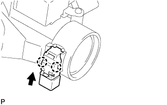
Engage the 2 claws to install the un-lock warning switch assembly to the steering lock sub-assembly.
-
-
INSTALL IGNITION SWITCH LOCK CYLINDER ASSEMBLY
-
Make sure that the ignition switch lock cylinder assembly is in the ACC position.
-
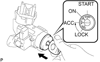
Install the ignition switch lock cylinder assembly to the steering lock sub-assembly.
-
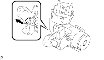
Make sure that the ignition switch lock cylinder assembly is securely installed.
-
-
INSPECT STEERING LOCK OPERATION
-
Check that the steering lock mechanism is activated when the key is removed.
-
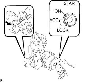
Check that the steering lock mechanism is deactivated when the key is inserted and turned to the ACC position.
Tech Tips
If there is any abnormality, replace the ignition switch lock cylinder assembly.
-
-
INSTALL STEERING COLUMN UPPER WITH SWITCH BRACKET ASSEMBLY
-
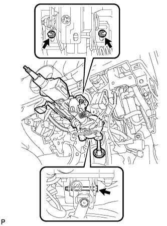
Temporarily install the assembled steering lock and its bracket to the steering column assembly with 2 new tapered-head bolts.
-
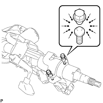
Tighten the 2 tapered-head bolts until the bolt heads break off.
-
-
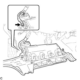
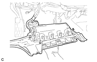
INSTALL TRANSPONDER KEY AMPLIFIER
-
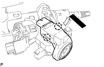
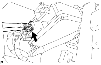
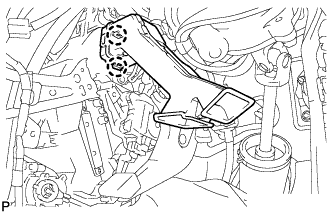
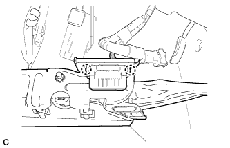
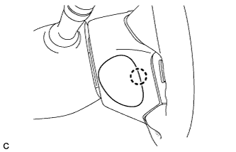
Align the transponder key amplifier with the upper bracket. Tilt the amplifier slightly and slide it into the position as shown in the illustration.
-
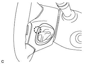
Push the transponder key amplifier to install it to the upper bracket with the 2 claws.
Note
Do not push the amplifier with excessive force.
-
-
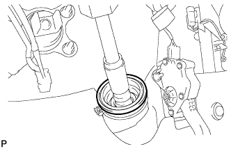
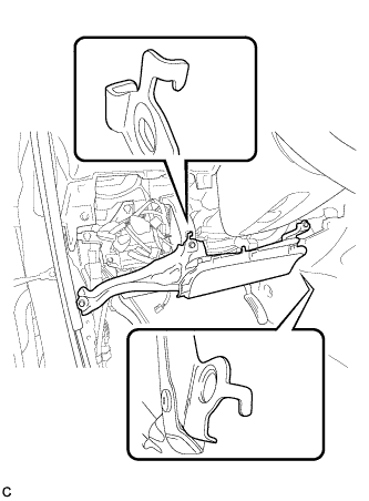
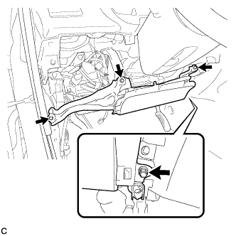
INSTALL STEERING INTERMEDIATE SHAFT ASSEMBLY
-
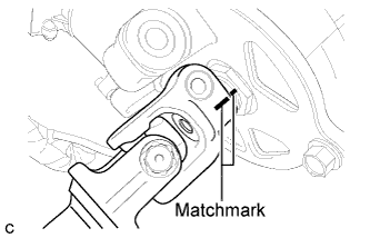
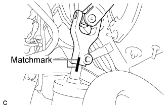
Align the matchmarks on the steering intermediate shaft sub-assembly and the steering column assembly.
-
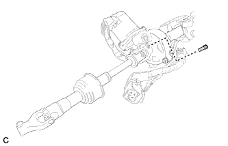
Install a new bolt.
- Torque:
- 35 N*m { 360 kgf*cm, 26 ft.*lbf }
-
-
INSTALL STEERING COLUMN ASSEMBLY (for LHD)
-
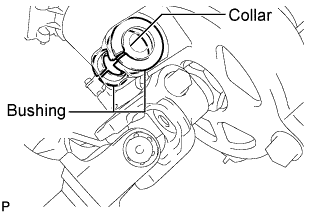
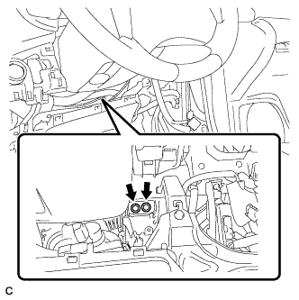
Check that the 2 bushings are securely installed to the steering column assembly.
Tech Tips
If the bushings are missing or damaged, replace the steering column assembly with a new one.
-
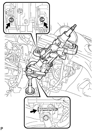
Install the steering column assembly with the bolt and 2 nuts.
- Torque:
- Bolt
- 36 N*m { 367 kgf*cm, 27 ft.*lbf }
- Nut
- 25 N*m { 255 kgf*cm, 18 ft.*lbf }
Note
There are two different bolt sizes (12 mm (0.472 in.) or 14 mm (0.551 in.)) available.
-
Connect the connectors and engage the wire harness clamps to the steering column assembly.
-
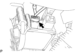
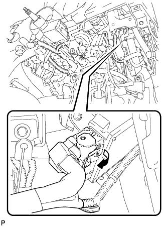
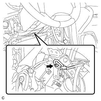
Connect the connector to the power steering ECU assembly.
-
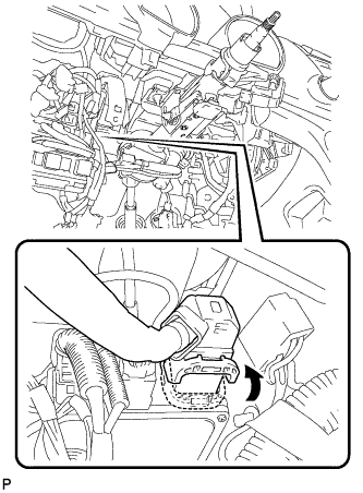
Connect the connector to the power steering ECU assembly.
Tech Tips
As shown in the illustration, securely return the lock lever to its original position to connect the connector.
-
-
INSTALL STEERING COLUMN ASSEMBLY (for RHD)
-
Check that the 2 bushings are securely installed to the steering column assembly.
Tech Tips
If the bushings are missing or damaged, replace the steering column assembly with a new one.
-
Install the steering column assembly with the bolt and 2 nuts.
- Torque:
- Bolt
- 36 N*m { 367 kgf*cm, 27 ft.*lbf }
- Nut
- 25 N*m { 255 kgf*cm, 18 ft.*lbf }
Note
There are two different bolt sizes (12 mm (0.472 in.) or 14 mm (0.551 in.)) available.
-
Connect the connectors and engage the wire harness clamps to the steering column assembly.
-
Connect the connector to the power steering ECU assembly.
-
Connect the connector to the power steering ECU assembly.
Tech Tips
As shown in the illustration, securely return the lock lever to its original position to connect the connector.
-
-
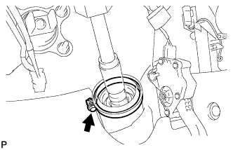
CONNECT STEERING INTERMEDIATE SHAFT SUB-ASSEMBLY
-
Align the matchmarks on the steering intermediate shaft sub-assembly and the power steering link assembly.
-
Install a new bolt.
- Torque:
- 35 N*m { 360 kgf*cm, 26 ft.*lbf }
-
Install the steering intermediate shaft sub-assembly to the steering column hole shield.
-
Tighten the bolt.
-
-
INSTALL NO. 1 AIR DUCT SUB-ASSEMBLY (for LHD)
-
Engage the 2 claws to install the No. 1 air duct sub-assembly.
-
-
INSTALL NO. 1 AIR DUCT SUB-ASSEMBLY (for RHD)
-
Engage the 2 claws to install the No. 1 air duct sub-assembly.
-
-
POSITION FRONT WHEELS STRAIGHT AHEAD
-
INSTALL TURN SIGNAL SWITCH ASSEMBLY WITH SPIRAL CABLE SUB-ASSEMBLY
-
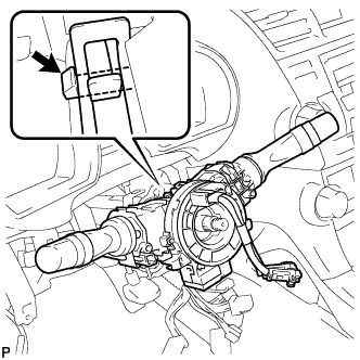
Using pliers, engage the claw. Install the turn signal switch assembly with spiral cable sub-assembly to the steering column assembly.
-
Connect the connectors to the turn signal switch assembly with spiral cable sub-assembly.
-
-
INSTALL STEERING COLUMN COVER
-
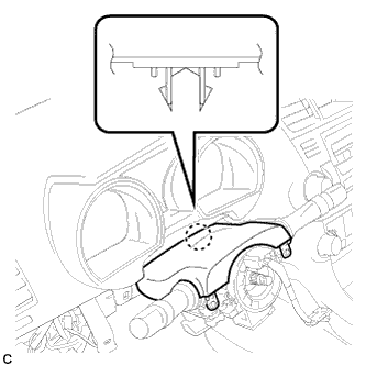
Engage the claw to install the upper steering column cover.
-
Engage the 2 claws to install the lower steering column cover.
-
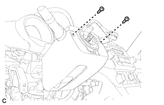
Install the 2 screws.
- Torque:
- 2.0 N*m { 20 kgf*cm, 18 in.*lbf }
-
-
INSTALL BRAKE PEDAL SUPPORT SUB-ASSEMBLY (for LHD)
-
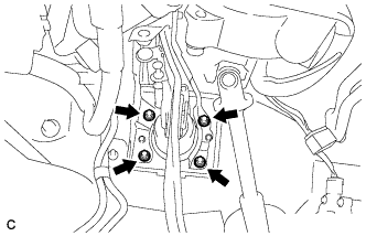
Install the brake pedal support sub-assembly with the 4 nuts.
- Torque:
- 13 N*m { 132 kgf*cm, 10 ft.*lbf }
-
Install the brake pedal support sub-assembly to the instrument panel reinforcement with the 2 bolts.
- Torque:
- 35 N*m { 357 kgf*cm, 26 ft.*lbf }
-
Connect the brake pedal load sensing switch connector and engage the clamp.
-
-
INSTALL BRAKE PEDAL SUPPORT SUB-ASSEMBLY (for RHD)
-
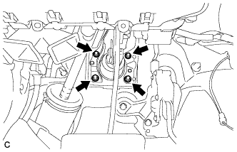
Install the brake pedal support sub-assembly with the 4 nuts.
- Torque:
- 13 N*m { 132 kgf*cm, 10 ft.*lbf }
-
Install the brake pedal support sub-assembly to the instrument panel reinforcement with the 2 bolts.
- Torque:
- 35 N*m { 357 kgf*cm, 26 ft.*lbf }
-
Connect the brake pedal load sensing switch connector and engage the clamp.
-
-
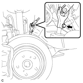
CONNECT BRAKE MASTER CYLINDER PUSH ROD CLEVIS
-
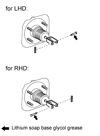
Apply lithium soap base glycol grease to the push rod pin.
-
Connect the brake master cylinder push rod clevis to the brake pedal with the push rod pin, and install a new clip as shown in the illustration.
-
-
INSTALL BRAKE PEDAL RETURN SPRING
-
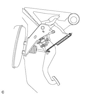
Install the brake pedal return spring between the instrument panel reinforcement and brake master cylinder push rod clevis.
-
-
INSTALL STOP LIGHT SWITCH ASSEMBLY
-
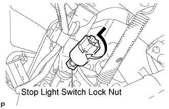
Temporarily install the stop light switch assembly with the stop light switch lock nut.
-
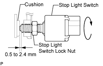
Turn the stop light switch assembly so that the clearance between the nut end and stop light switch cushion is between 0.5 to 2.4 mm (0.020 to 0.095 in.).
-
Tighten the stop light switch lock nut.
- Torque:
- 17 N*m { 173 kgf*cm, 12 ft.*lbf }
-
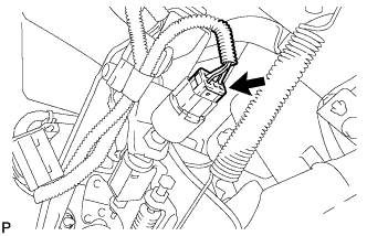
Connect the connector.
-
-
INSPECT AND ADJUST BRAKE PEDAL HEIGHT
-
Check the brake pedal height.
-
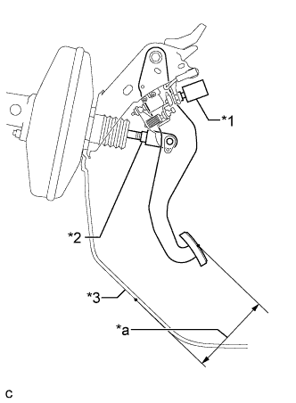
Text in Illustration *1 Stop Light Switch Assembly *2 Clevis Lock Nut *3 Front Floor Footrest (for LHD) No. 2 Dash Panel Insulator Pad (for RHD) *a Brake Pedal Height Turn back the carpet.
-
Measure the shortest distance between the brake pedal surface and front floor footrest (for LHD) or No. 2 dash panel insulator pad (for RHD).
Pedal height (for LHD: from front floor footrest, for RHD: from No. 2 dash panel insulator pad) Model Specified Condition LHD 148.8 to 158.8 mm (5.858 to 6.252 in.) RHD 165.9 to 175.9 mm (6.531 to 6.925 in.)
-
-
Adjust the brake pedal height.
-
Disconnect the stop light switch connector.
-
Remove the stop light switch assembly.
-
Loosen the push rod clevis lock nut.
-
Adjust the brake pedal height by turning the push rod.
-
Tighten the push rod clevis lock nut.
- Torque:
- 26 N*m { 265 kgf*cm, 19 ft.*lbf }
-
Install and adjust the stop light switch Click here.
Note
Do not depress the brake pedal.
-
Connect the stop light switch connector.
-
-
-
INSPECT BRAKE PEDAL FREE PLAY
-
Stop the engine. Depress the pedal several times until no vacuum is left in the brake booster. Release the brake pedal.
-
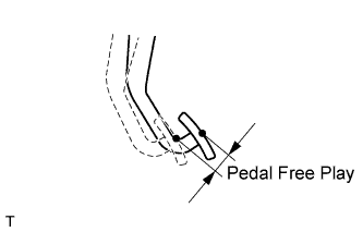
Depress the pedal until a slight resistance is felt. Measure the distance as shown in the illustration.
Pedal free play 1.0 to 6.0 mm (0.039 to 0.236 in.) If the pedal free play is not as specified, check the stop light switch clearance Click here. If the pedal free play is as specified, proceed to the "INSPECT BRAKE PEDAL RESERVE DISTANCE" procedure.
-
-
INSPECT BRAKE PEDAL RESERVE DISTANCE
Tech Tips
Measure the distance at the same point used for the brake pedal height inspection.
-
Release the parking brake.
-
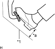
Text in Illustration *1 Front Floor Footrest (for LHD) No. 2 Dash Panel Insulator Pad (for RHD) *a Pedal Reserve Distance With the engine running, depress the brake pedal and measure the pedal reserve distance as shown in the illustration.
Pedal reserve distance at 500 N (51 kgf, 112 lbf) (for LHD: from front floor footrest, for RHD: from No. 2 dash panel insulator pad) Model Specified Condition LHD 84.4 mm (3.32 in.) RHD 97.8 mm (3.85 in.) If the distance is not as specified, troubleshoot the brake system Click here.
-
-
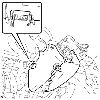
INSTALL DRIVER SIDE KNEE AIRBAG ASSEMBLY
-
Check that the ignition switch is off.
-
Check that the battery negative (-) cable is disconnected.
CAUTION:
Wait for at least 90 seconds after disconnecting the cable to prevent airbag deployment.
-
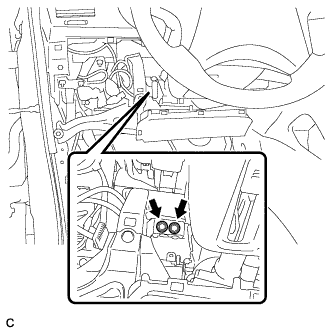
Install the DLC3 to the driver side knee airbag assembly with the 2 claws.
-
Connect the connector to the driver side knee airbag assembly.
Note
When handling the airbag connector, take care not to damage the airbag wire harness.
-
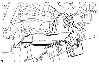
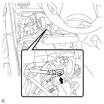
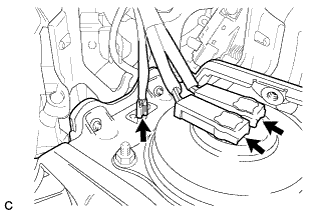
Support the driver side knee airbag assembly with one hand as shown in the illustration.
-
Temporarily install the driver side knee airbag assembly with the 2 hooks.
-
Install the driver side knee airbag assembly with the 4 bolts.
- Torque:
- 10 N*m { 102 kgf*cm, 7 ft.*lbf }
-
-
INSTALL LOWER INSTRUMENT PANEL FINISH PANEL SUB-ASSEMBLY (for Manual Air Conditioning System)
-

Connect the hood lock control cable assembly.
-
Connect each connector.
-
Engage the 3 claws and 10 clips.
-
Install the lower instrument panel finish panel sub-assembly with the 2 bolts <B>.
-
-
INSTALL LOWER INSTRUMENT PANEL FINISH PANEL SUB-ASSEMBLY (for Automatic Air Conditioning System)
-

Connect the hood lock control cable assembly.
-
Connect each connector and the aspirator duct.
-

Engage the 3 claws and 10 clips.
-
Install the lower instrument panel finish panel sub-assembly with the 2 bolts <B>.
-
-
INSTALL COWL SIDE TRIM SUB-ASSEMBLY LH
-

Engage the claw and clip, install the cowl side trim sub-assembly LH.
-
Install the clip.
-
-
INSTALL FRONT DOOR SCUFF PLATE LH
-

Engage the guide and 8 claws, and install the front door scuff plate LH.
-
-
ADJUST SPIRAL CABLE
-
Check that the ignition switch is off.
-
Check that the battery negative (-) cable is disconnected.
CAUTION:
Wait for at least 90 seconds after disconnecting the cable to prevent airbag deployment.
-
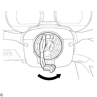
Rotate the spiral cable counterclockwise slowly by hand until it stops.
Note
Do not turn the spiral cable using the airbag wire harness.
-
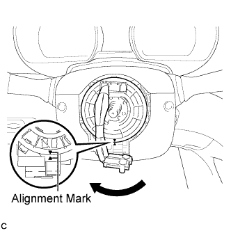
Rotate the spiral cable clockwise approximately 2.5 turns to align the marks.
Note
Do not turn the spiral cable using the airbag wire harness.
Tech Tips
The spiral cable will rotate approximately 2.5 turns to both the left and right from the center.
-
-
INSTALL STEERING WHEEL ASSEMBLY
-
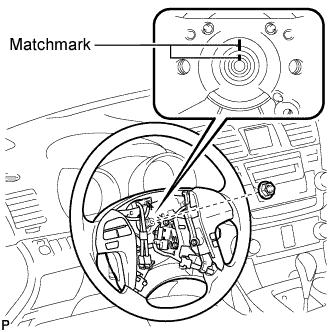
Align the matchmarks on the steering wheel assembly and steering main shaft.
-
Install the steering wheel assembly set nut.
- Torque:
- 50 N*m { 510 kgf*cm, 37 ft.*lbf }
-
Connect the connectors to the spiral cable sub-assembly.
-
-
INSPECT STEERING WHEEL CENTER POINT
-
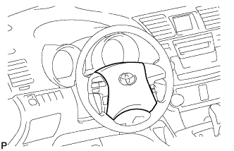
INSTALL STEERING PAD
-
Check that the ignition switch is off.
-
Check that the battery negative (-) terminal is disconnected.
CAUTION:
Wait for at least 90 seconds after disconnecting the cable to prevent airbag deployment.
-
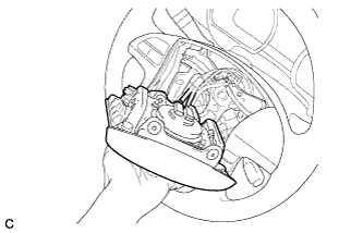
Support the steering pad with one hand as shown in the illustration.
-
Connect the 2 airbag connectors to the steering pad.
Note
When handling the airbag connector, take care not to damage the airbag wire harness.
-
Connect the horn connector to the steering pad.
-
Confirm that the circumference groove of the "TORX" screw fits in the screw case, and place the steering pad onto the steering wheel assembly.
-
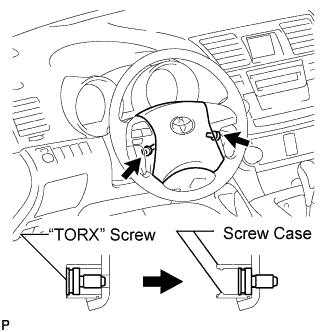
Using a "TORX" socket wrench (T30), tighten the 2 "TORX" screws.
- Torque:
- 8.8 N*m { 90 kgf*cm, 78 in.*lbf }
-
-
INSTALL LOWER NO. 3 STEERING WHEEL COVER
-
Install the lower No. 3 steering wheel cover with the claw.
-
-
INSTALL LOWER NO. 2 STEERING WHEEL COVER
-
Install the lower No. 2 steering wheel cover with the claw.
-
-
INSTALL FRONT WHEEL LH
-
CONNECT CABLE TO NEGATIVE BATTERY TERMINAL
Note
When disconnecting the cable, some systems need to be initialized after the cable is reconnected Click here.
-
INSPECT STEERING PAD
-
With the steering pad installed on the vehicle, perform a visual check. If there are any defects as mentioned below, replace the steering pad with a new one:
-
Cuts, minute cracks or marked discoloration on the steering pad top surface or grooves.
-
-
Make sure that the horn sounds.
Tech Tips
If the horn does not sound, inspect the horn system Click here.
-
-
INSPECT SRS WARNING LIGHT
-
Inspect the SRS warning light Click here.
-