UNLOCK WARNING SWITCH REMOVAL
-
POSITION FRONT WHEELS STRAIGHT AHEAD
-
DISCONNECT CABLE FROM NEGATIVE BATTERY TERMINAL
CAUTION:
Wait at least 90 seconds after disconnecting the cable from the negative (-) battery terminal to prevent airbag and seat belt pretensioner activation Click here.
Note
When disconnecting the cable, some systems need to be initialized after the cable is reconnected Click here.
-
REMOVE FRONT WHEEL LH
-
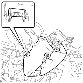
REMOVE LOWER NO. 3 STEERING WHEEL COVER
-
Disengage the claw and remove the lower No. 3 steering wheel cover.
-
-
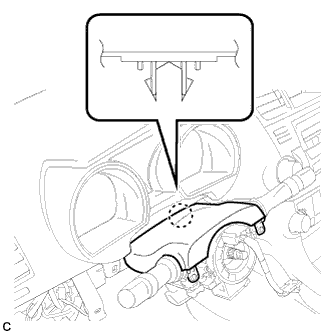
REMOVE LOWER NO. 2 STEERING WHEEL COVER
-
Disengage the claw and remove the lower No. 2 steering wheel cover.
-
-
REMOVE STEERING PAD
-
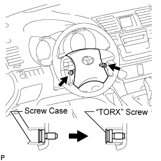
Using a "TORX" socket wrench (T30), loosen the 2 "TORX" screws until the groove along the screw circumference catches on the screw case.
-
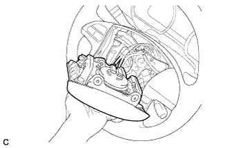
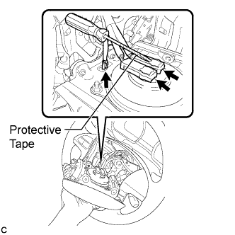
Pull out the steering pad from the steering wheel assembly and support the steering pad with one hand as shown in the illustration.
Note
When removing the steering pad, do not pull the airbag wire harness.
-
Disconnect the horn connector from the steering pad.
-
Using a screwdriver with the tip wrapped with protective tape, disconnect the 2 airbag connectors and remove the steering pad.
Note
When handling the airbag connector, take care not to damage the airbag wire harness.
-
-
REMOVE STEERING WHEEL ASSEMBLY
-
Remove the steering wheel assembly set nut.
-
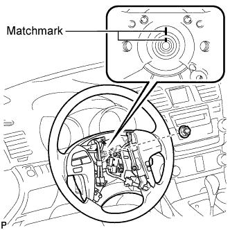
Put matchmarks on the steering wheel assembly and the steering main shaft.
-
Disconnect the connectors from the spiral cable.
-
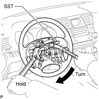
Using SST, remove the steering wheel assembly.
- SST
- 09950-50013 ( 09951-05010, 09952-05010, 09953-05020, 09954-05021 )
Note
Apply a small amount of grease to the threads and tip of SST (09953-05020) before use.
-
-
REMOVE FRONT DOOR SCUFF PLATE LH
-

Disengage the 8 claws and guide, and remove the front door scuff plate LH.
-
-
REMOVE COWL SIDE TRIM SUB-ASSEMBLY LH
-

Remove the clip.
-
Disengage the clip and claw, and remove the cowl side trim sub-assembly LH.
-
-
REMOVE LOWER INSTRUMENT PANEL FINISH PANEL SUB-ASSEMBLY (for Manual Air Conditioning System)
-

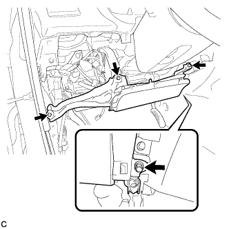
Remove the 2 bolts <B>.
-
Disengage the 3 claws and 10 clips.
-
Disconnect each connector.
-
Disconnect the hood lock control cable assembly and remove the lower instrument panel finish panel sub-assembly.
-
-
REMOVE LOWER INSTRUMENT PANEL FINISH PANEL SUB-ASSEMBLY (for Automatic Air Conditioning System)
-

Remove the 2 bolts <B>.
-
Disengage the 3 claws and 10 clips.
-

Disconnect each connector and the aspirator duct.
-
Disconnect the hood lock control cable assembly and remove the lower instrument panel finish panel sub-assembly.
-
-
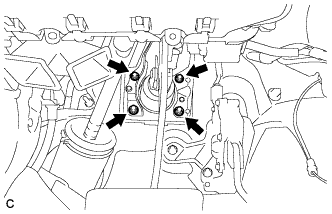
REMOVE DRIVER SIDE KNEE AIRBAG ASSEMBLY
-
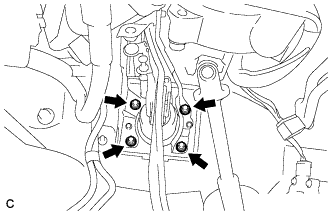
Remove the 4 bolts.
-
Disengage the 2 hooks.
-
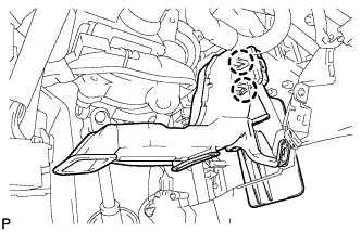
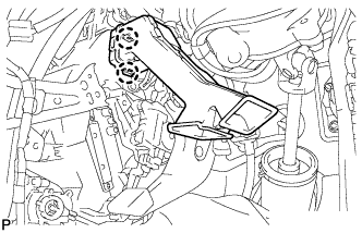
Pull out the driver side knee airbag assembly from the vehicle and support the driver side knee airbag assembly with one hand as shown in the illustration.
Note
When removing the driver side knee airbag assembly, do not pull the airbag wire harness.
-
Using a screwdriver with the tip wrapped with protective tape, disconnect the driver side knee airbag connector.
Note
When handling the airbag connector, take care not to damage the airbag wire harness.
-
Disengage the 2 claws and separate the DLC3 from the driver side knee airbag assembly.
-
-
REMOVE BRAKE PEDAL RETURN SPRING
-
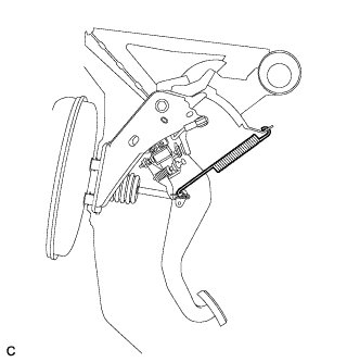
Remove the brake pedal return spring from the push rod pin and instrument panel reinforcement.
-
-
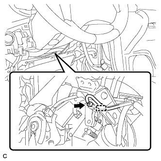
REMOVE STOP LIGHT SWITCH ASSEMBLY
-
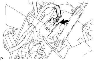
Disconnect the connector.
-
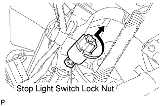
Loosen the stop light switch lock nut.
-
Remove the stop light switch assembly as shown in the illustration.
-
-
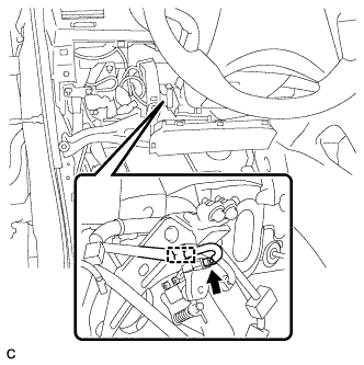
SEPARATE BRAKE MASTER CYLINDER PUSH ROD CLEVIS
-
Remove the clip and push rod pin, and separate the brake master cylinder push rod clevis from the brake pedal sub-assembly.
-
-
REMOVE BRAKE PEDAL SUPPORT SUB-ASSEMBLY (for LHD)
-
Disconnect the brake pedal load sensing switch connector and disengage the clamp.
-
Remove the 2 bolts and separate the brake pedal support sub-assembly from the instrument panel reinforcement.
-
Remove the 4 nuts and brake pedal support sub-assembly from the body.
-
-
REMOVE BRAKE PEDAL SUPPORT SUB-ASSEMBLY (for RHD)
-
Disconnect the brake pedal load sensing switch connector and disengage the clamp.
-
Remove the 2 bolts and separate the brake pedal support sub-assembly from the instrument panel reinforcement.
-
Remove the 4 nuts and brake pedal support sub-assembly from the body.
-
-
REMOVE STEERING COLUMN COVER
-
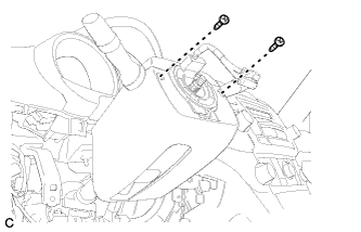
Remove the 2 screws.
-
Disengage the 2 claws to remove the lower steering column cover.
-
Disengage the claw to remove the upper steering column cover.
-
-
REMOVE TURN SIGNAL SWITCH ASSEMBLY WITH SPIRAL CABLE
-
Disconnect the connectors from the turn signal switch assembly with spiral cable sub-assembly.
-
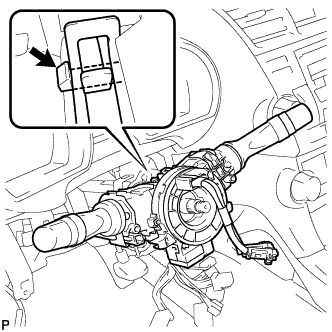
Using pliers, grip the claws of the clip and remove the turn signal switch assembly with spiral cable sub-assembly.
-
-
REMOVE NO. 1 AIR DUCT SUB-ASSEMBLY (for LHD)
-
Disengage the 2 claws and remove the No. 1 air duct sub-assembly.
-
-
REMOVE NO. 1 AIR DUCT SUB-ASSEMBLY (for RHD)
-
Disengage the 2 claws and remove the No. 1 air duct sub-assembly.
-
-
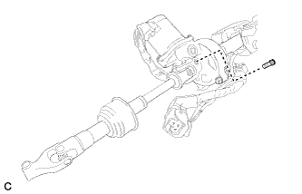
SEPARATE STEERING INTERMEDIATE SHAFT SUB-ASSEMBLY
-
Loosen the bolt.
-
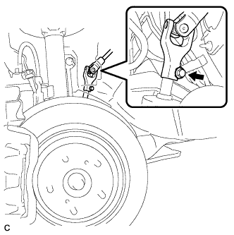
Remove the bolt and slide the steering intermediate shaft sub-assembly.
Note
Do not separate the steering intermediate shaft sub-assembly from the power steering link assembly.
-
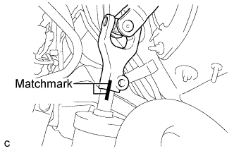
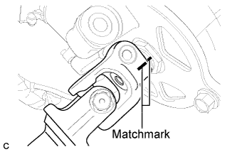
Put matchmarks on the steering intermediate shaft sub-assembly and the power steering link assembly.
-
Separate the steering intermediate shaft sub-assembly from the power steering link assembly.
-
-
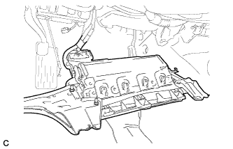
REMOVE STEERING COLUMN ASSEMBLY (for LHD)
-
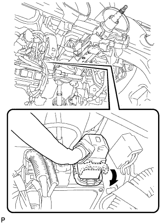
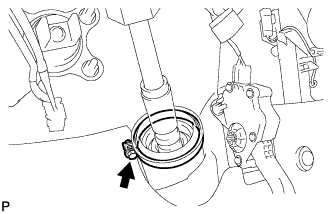
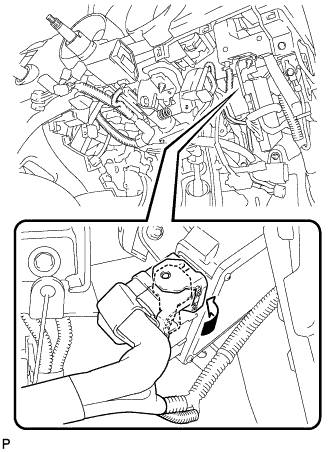
Disconnect the connector from the power steering ECU assembly.
Tech Tips
As shown in the illustration, turn the lock lever to disconnect the connector.
-
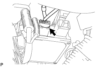
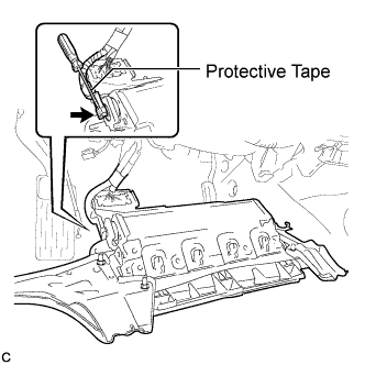
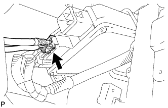
Disconnect the connector from the power steering ECU assembly.
-
Disconnect the connectors and disengage the wire harness clamps from the steering column assembly.
-
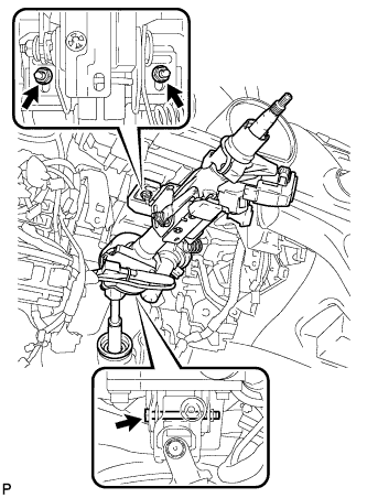
Remove the bolt, 2 nuts, and the steering column assembly.
-
-
REMOVE STEERING COLUMN ASSEMBLY (for RHD)
-
Disconnect the connector from the power steering ECU assembly.
Tech Tips
As shown in the illustration, turn the lock lever to disconnect the connector.
-
Disconnect the connector from the power steering ECU assembly.
-
Disconnect the connectors and disengage the wire harness clamps from the steering column assembly.
-
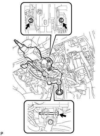
Remove the bolt, 2 nuts, and the steering column assembly.
-
-
REMOVE STEERING INTERMEDIATE SHAFT ASSEMBLY
-
Remove the bolt.
-
Put matchmarks on the steering intermediate shaft assembly and the steering column assembly.
-
Remove the steering intermediate shaft assembly from the steering column assembly.
-
-
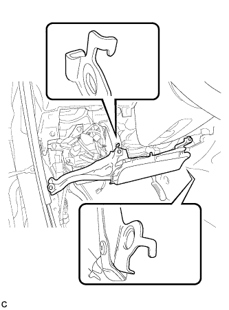
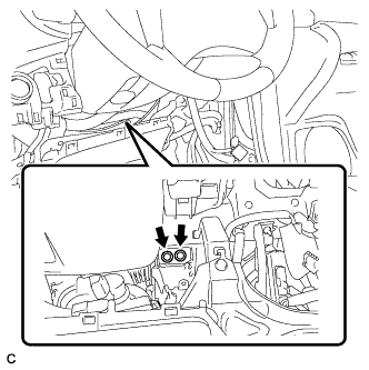
REMOVE TRANSPONDER KEY AMPLIFIER
-
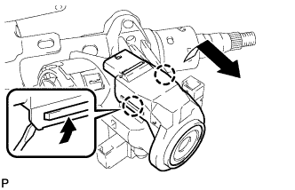
Using a screwdriver, widen the claws hanging onto the upper bracket by approximately 1.0 mm (0.039 in.).
-
Pull out the transponder key amplifier with the claw open.
Note
Using excessive force may damage the case.
-
-
REMOVE UPPER STEERING COLUMN WITH SWITCH BRACKET ASSEMBLY
-
Secure the steering column assembly in a vise.
-
Using a center punch, mark the center of the 2 tapered-head bolts.
-
Using a 3 to 4 mm (0.12 to 0.16 in.) diameter drill bit, drill a hole in each tapered-head bolt.
-

Using a screw extractor, remove the 2 tapered-head bolts, and then remove the steering column upper with switch bracket assembly and the steering lock bracket from the steering column assembly.
-
-
REMOVE IGNITION SWITCH LOCK CYLINDER ASSEMBLY
-
Turn the ignition switch lock cylinder assembly to the ACC position.
-
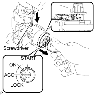
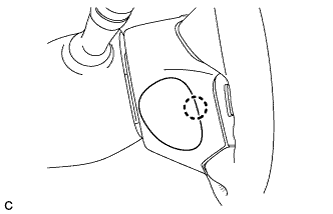
Insert a screwdriver into the hole of the steering column upper with switch bracket assembly as shown in the illustration. Pull the ignition switch lock cylinder assembly until its claw contacts the stopper of the steering column upper with switch bracket assembly.
Note
Make sure to pull the ignition switch lock cylinder assembly until its claw contacts the stopper of the steering column upper with switch bracket assembly. Failure to do so will affect later work operations.
-
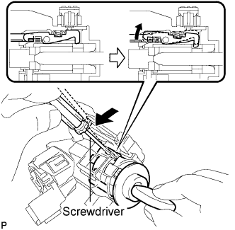
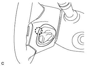
Insert a screwdriver into the hole of the steering column upper with switch bracket assembly. Push the screwdriver downward as shown in the illustration to disengage the claw of the ignition switch lock cylinder assembly, and pull out the ignition switch lock cylinder assembly.
-
-
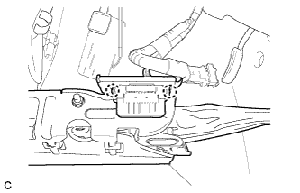
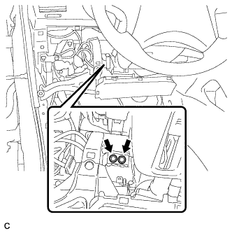
REMOVE UNLOCK WARNING SWITCH ASSEMBLY
-
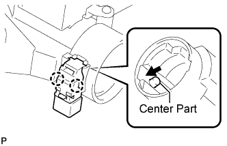
Remove the un-lock warning switch assembly by pushing up the center part and releasing the 2 claws.
-