SMART ENTRY AND START SYSTEM Front Passenger Side Door Entry Lock Function does not Operate
DESCRIPTION
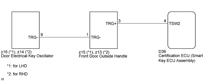
If the front passenger side door entry lock function does not operate but the entry unlock function operates, the communication line between the vehicle and electrical key transmitter is normal. As a faulty part, the entry lock switch circuit (certification ECU (smart key ECU assembly) → passenger side door outside handle (entry lock switch) → passenger side door electrical key oscillator) can be considered.
WIRING DIAGRAM
INSPECTION PROCEDURE
Note
Before performing the inspection, check that there are no problems related to "CAN COMMUNICATION SYSTEM" and "LIN COMMUNICATION SYSTEM".
PROCEDURE
-
CHECK POWER DOOR LOCK OPERATION
-
When the door control switch on the master switch assembly is operated, check that the locked doors unlock Click here.
OK Locked doors unlock.
NG 
GO TO POWER DOOR LOCK CONTROL SYSTEM Click here
OK 
-
-
READ VALUE USING INTELLIGENT TESTER (DOOR LOCK POSITION SWITCH)
-
Connect the intelligent tester to the DLC3.
-
Turn the engine switch on (IG).
-
Turn the intelligent tester on.
-
Enter the following menus: Body / Main Body / Data List.
-
Read the Data List according to the display on the intelligent tester.
Main Body (Main Body ECU (Instrument Panel Junction Block)) Tester Display Measurement Item/Range Normal Condition Diagnostic Note P-Door Lock Pos SW Front passenger side door lock position switch signal/ON or OFF ON: Front passenger side door is unlocked
OFF: Front passenger side door is locked
- OK On the intelligent tester screen, the display changes between ON and OFF as shown in the chart above. Result Result Proceed to OK A NG B
(Proceed to "Front Passenger Door LOCK/UNLOCK Functions do not Operate")
B
GO TO POWER DOOR LOCK CONTROL SYSTEM Click here
A
-
-
READ VALUE ON INTELLIGENT TESTER (DOOR OUTSIDE HANDLE)
-
Select P Trigger SW in the Data List and read the tester display.
Entry & Start (Certification ECU (Smart Key ECU Assembly)): Tester Display Measurement Item/Range Normal Condition Diagnostic Note P Trigger SW Front passenger side door lock switch / ON or OFF ON: Entry lock switch is pressed
OFF: Entry lock switch is not pressed
- OK On the tester screen, the item changes between ON and OFF according to the chart above.
NG 
CHECK HARNESS AND CONNECTOR (FRONT DOOR OUTSIDE HANDLE - DOOR ELECTRICAL KEY OSCILLATOR) Click here
OK 
REPLACE CERTIFICATION ECU (SMART KEY ECU ASSEMBLY)
-
-
CHECK HARNESS AND CONNECTOR (FRONT DOOR OUTSIDE HANDLE - DOOR ELECTRICAL KEY OSCILLATOR)
-
Remove the front door outside handle Click here.
-
Disconnect the door electrical key oscillator connector.
-
Measure the resistance according to the value(s) in the table below.
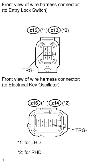
Standard resistance for LHD Tester Connection Condition Specified Condition z15-1 (TRG-) - z16-9 (TRG-) Always Below 1 Ω z15-1 (TRG-) - Body ground Always 10 kΩ or higher for RHD Tester Connection Condition Specified Condition z13-1 (TRG-) - z14-9 (TRG-) Always Below 1 Ω z13-1 (TRG-) - Body ground Always 10 kΩ or higher
NG
REPAIR OR REPLACE HARNESS OR CONNECTOR
OK
-
-
CHECK HARNESS AND CONNECTOR (CERTIFICATION ECU - FRONT DOOR OUTSIDE HANDLE)
-
Disconnect the certification ECU (smart key ECU assembly) connector.
-
Measure the resistance according to the value(s) in the table below.
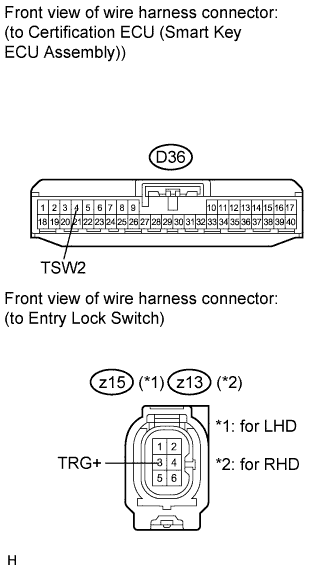
Standard resistance for LHD Tester Connection Condition Specified Condition D36-4 (TSW2) - z15-3 (TRG+) Always Below 1 Ω D36-4 (TSW2) - Body ground Always 10 kΩ or higher for RHD Tester Connection Condition Specified Condition D36-4 (TSW2) - z13-3 (TRG+) Always Below 1 Ω D36-4 (TSW2) - Body ground Always 10 kΩ or higher
NG
REPAIR OR REPLACE HARNESS OR CONNECTOR
OK
-
-
INSPECT FRONT DOOR OUTSIDE HANDLE (FRONT PASSENGER SIDE)
-
Measure the resistance according to the value(s) in the table below.
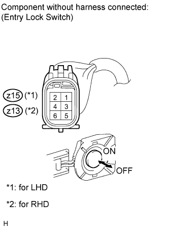
Standard resistance for LHD Tester Connection Condition Specified Condition z15-1 (TRG-) - z15-3 (TRG+) Lock switch not pushed 10 kΩ or higher z15-1 (TRG-) - z15-3 (TRG+) Lock switch pushed Below 1 Ω for RHD Tester Connection Condition Specified Condition z13-1 (TRG-) - z13-3 (TRG+) Lock switch not pushed 10 kΩ or higher z13-1 (TRG-) - z13-3 (TRG+) Lock switch pushed Below 1 Ω
NG
REPLACE FRONT DOOR OUTSIDE HANDLE Click here
OK
-
-
REPLACE DOOR ELECTRICAL KEY OSCILLATOR
-
Replace the door electrical key oscillator Click here.
NEXT
-
-
CHECK DOOR ELECTRICAL KEY OSCILLATOR (OPERATION)
-
Check that the entry functions operate normally.
OK Entry functions operate normally.
NG
REPLACE CERTIFICATION ECU (SMART KEY ECU ASSEMBLY)
OK
END (DOOR ELECTRICAL KEY OSCILLATOR IS DEFECTIVE)
-