| DTC Code | DTC Name |
|---|---|
| Key Reminder Buzzer does not Sound |
DESCRIPTION
The key reminder warning buzzer sounds when the driver side door is opened while the ignition switch is in the LOCK or ACC positions. The key reminder warning buzzer is activated when the main body ECU sends a key switch signal and driver side courtesy switch signal to the combination meter.
Since the key reminder warning system has functions that use CAN communication, first confirm that there is no malfunction in the communication system by inspecting the CAN communication functions in accordance with the "HOW TO PROCEED WITH TROUBLESHOOTING" procedures. Then, conduct the following inspection procedure.
INSPECTION PROCEDURE
PROCEDURE
- Click here
READ VALUE USING INTELLIGENT TESTER (FRONT DOOR COURTESY LIGHT SWITCH)
-
Check the Data List for proper functioning of the driver side door courtesy light switch.
Table 1. MAIN BODY Tester Display Measurement Item/Range Normal Condition Diagnostic Note D Door Courtesy SW Front door courtesy light switch signal / ON or OFF ON: Driver side door is open
OFF: Driver side door is closed
- OK ON (driver door is open) appears on the screen.
- OKClick here
- NGClick here
-
- Click here
READ VALUE USING INTELLIGENT TESTER (UNLOCK WARNING SWITCH)
-
Check the Data List for proper functioning of the unlock warning switch.
Table 2. MAIN BODY Tester Display Measurement Item/Range Normal Condition Diagnostic Note Key Unlock Warning SW Unlock warning switch signal / ON or OFF ON: Key is in ignition key cylinder
OFF: No key is in ignition key cylinder
- OK ON (Key is in ignition key cylinder) appears on the screen.
- OKClick here
- NGClick here
-
- Click here
INSPECT UNLOCK WARNING SWITCH ASSEMBLY
-
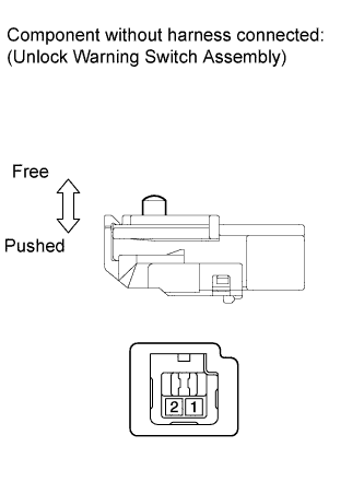
Remove the unlock warning switch assembly (Click here).
-
Measure the resistance according to the value(s) in the table below.
Standard resistance Tester Connection Switch Condition Specified Condition 1 - 2 Switch free (Key removed) 10 kΩ or higher 1 - 2 Switch pushed (Key set) Below 1 Ω
- OKClick here
- NGClick here
-
- Click here
CHECK HARNESS AND CONNECTOR (UNLOCK WARNING SWITCH - MAIN BODY ECU)
-
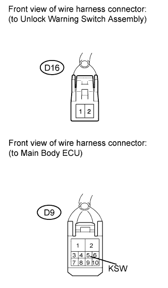
Disconnect the D16 unlock warning switch assembly and D9 ECU connectors.
-
Measure the resistance according to the value(s) in the table below.
Standard resistance Tester Connection Condition Specified Condition D16-1 - D9-5 (KSW) Always Below 1 Ω D16-1 - Body ground 10 kΩ or higher
- OKClick here
- NGClick here
-
- Click here
REPLACE INSTRUMENT PANEL JUNCTION BLOCK (MAIN BODY ECU)
- Click here
INSPECT FRONT DOOR COURTESY LIGHT SWITCH (for Driver Side)
-
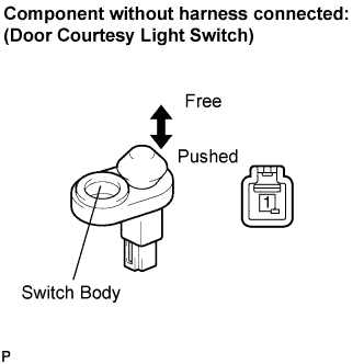
Remove the driver's side front door courtesy light switch (Click here).
-
Measure the resistance according to the value(s) in the table below.
Standard resistance Tester Connection Condition Specified Condition 1 - Switch body Courtesy switch pushed (Door closed) 10 kΩ or higher Courtesy switch free (Door open) Below 1 Ω
- OKClick here
- NGClick here
-
- Click here
CHECK HARNESS AND CONNECTOR (FRONT DOOR COURTESY LIGHT SWITCH - MAIN BODY ECU)
-
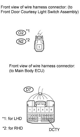
Disconnect the D7 ECU connector.
-
Measure the resistance according to the value(s) in the table below.
Standard resistance Table 3. for LHD Tester Connection Condition Specified Condition O2-1 - D7-24 (DCTY) Always Below 1 Ω O2-1 - Body ground 10 kΩ or higher Table 4. for RHD Tester Connection Condition Specified Condition N2-1 - D7-24 (DCTY) Always Below 1 Ω N2-1 - Body ground 10 kΩ or higher
- OKClick here
- NGClick here
-
- Click here
REPLACE INSTRUMENT PANEL JUNCTION BLOCK (MAIN BODY ECU)
- Click here
REPAIR OR REPLACE HARNESS OR CONNECTOR
- Click here
REPLACE FRONT DOOR COURTESY LIGHT SWITCH (for Driver Side)Click here
- Click here
REPAIR OR REPLACE HARNESS OR CONNECTOR
- Click here
REPLACE UNLOCK WARNING SWITCH ASSEMBLYClick here
- Click here
REPLACE COMBINATION METER ASSEMBLY