KEY REMINDER WARNING SYSTEM TERMINALS OF ECU
-
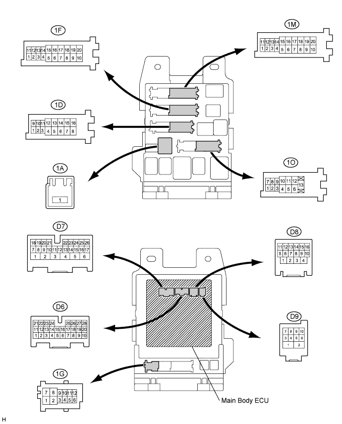
CHECK MAIN BODY ECU (INSTRUMENT PANEL JUNCTION BLOCK)
-
Disconnect the 1D, 1F junction block and and D7, D9 ECU connectors.
-
Measure the resistance and voltage according to the value(s) in the table below.
Tester Connection Wiring Color Terminal Description Condition Specified Condition 1F-10 (GND1) - Body ground W-B - Body ground Ground Always Below 1 Ω 1D-10 (BECU) - Body ground W - Body ground Power Source Always 11 to 14 V D7-24 (DCTY)*1- Body ground
G - Body ground Driver door courtesy light switch signal Switch pushed (Door closed) 10 kΩ or higher Switch free (Door opened) Below 1 Ω D7-24 (DCTY)*2- Body ground
SB - Body ground Driver door courtesy light switch signal Switch pushed (Door closed) 10 kΩ or higher Switch free (Door opened) Below 1 Ω D9-5 (KSW) - Body ground GR - Body ground Key unlock warning switch signal No key is in ignition key cylinder 10 kΩ or higher Key is in ignition key cylinder Below 1 Ω Tech Tips
*1: for LHD
*2: for RHD
Tech Tips
If the result is not as specified, there may be a malfunction on the wire harness side.
-