WIRELESS DOOR LOCK CONTROL SYSTEM (w/o Smart Entry and Start System), Diagnostic DTC:B1242
| DTC Code | DTC Name |
|---|---|
| B1242 | Wireless Door Lock Tuner Circuit Malfunction |
DESCRIPTION
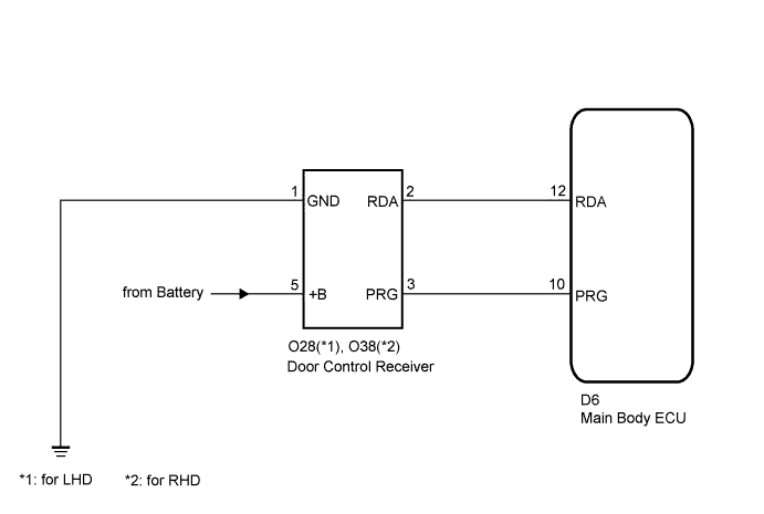
The door control receiver receives signals from the transmitter and sends these signals to the main body ECU.
| DTC No. | DTC Detection Condition | Trouble Area |
|---|---|---|
| B1242 | In diagnostic mode, an applicable RDA signal cannot be received within 1 second after a PRG signal has been output from the main body ECU. |
|
WIRING DIAGRAM
INSPECTION PROCEDURE
PROCEDURE
-
CHECK HARNESS AND CONNECTOR (MAIN BODY ECU - DOOR CONTROL RECEIVER)
-
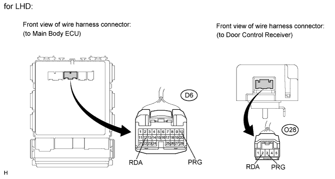
for LHD:
-
Disconnect the D6 main body ECU connector and the O28 door control receiver connector.
-
Measure the resistance according to the value(s) in the table below.
Standard resistance Tester Connection Condition Specified Condition D6-12 (RDA) - O28-2 (RDA) Always Below 1 Ω D6-12 (RDA) - Body ground Always 10 kΩ or higher D6-10 (PRG) - O28-3 (PRG) Always Below 1 Ω D6-10 (PRG) - Body ground Always 10 kΩ or higher
-
-
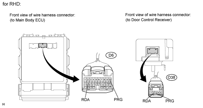
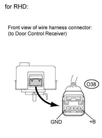
for RHD:
-
Disconnect the D6 main body ECU connector and the O38 door control receiver connector.
-
Measure the resistance according to the value(s) in the table below.
Standard resistance Tester Connection Condition Specified Condition D6-12 (RDA) - O38-2 (RDA) Always Below 1 Ω D6-12 (RDA) - Body ground Always 10 kΩ or higher D6-10 (PRG) - O38-3 (PRG) Always Below 1 Ω D6-10 (PRG) - Body ground Always 10 kΩ or higher
-
NG 
REPAIR OR REPLACE HARNESS OR CONNECTOR
OK 
-
-
CHECK HARNESS AND CONNECTOR (BATTERY, BODY GROUND)
-
for LHD:
-
Measure the voltage and resistance according to the value(s) in the table below.
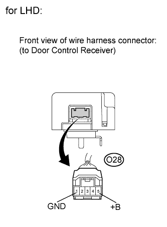
Standard Tester Connection Condition Specified Condition O28-1 (GND) - Body ground Always Below 1 Ω O28-5 (+B) - Body ground Always 11 to 14 V
-
-
for RHD:
-
Measure the voltage and resistance according to the value(s) in the table below.
Standard Tester Connection Condition Specified Condition O38-1 (GND) - Body ground Always Below 1 Ω O38-5 (+B) - Body ground Always 11 to 14 V
-
NG
REPAIR OR REPLACE HARNESS OR CONNECTOR
OK
-
-
REPLACE DOOR CONTROL RECEIVER
-
Reconnect the D6 main body ECU connector.
-
Replace the door control receiver with a normal one Click here.
-
Perform the registration procedures Click here.
Tech Tips
If a normally functioning door control receiver is available, connect it and check if the wireless door lock function is normal or DTCs are output. If the alternative receiver functions normally, replace the original door control receiver.
NEXT
-
-
CONFIRM DTC
-
Clear the DTCs Click here.
-
Check if the same DTC is detected.
Tech Tips
Reinstall the sensors, connectors, etc. and restore the previous vehicle conditions before rechecking for DTCs.
Result Result Proceed to DTC is output A DTC is not output B
B
USE SIMULATION METHOD TO CHECK Click here
A 
REPLACE MAIN BODY ECU (INSTRUMENT PANEL JUNCTION BLOCK)
-