WIRELESS DOOR LOCK CONTROL SYSTEM (w/ Smart Entry and Start System) No Answer-Back
DESCRIPTION
In some cases, wireless door lock control functions are normal but the hazard warning lights and/or wireless door lock buzzer answer-back function(s) does not operate. In such cases, the certification ECU's (smart key ECU assembly) hazard warning lights and wireless door lock buzzer signal outputs may be malfunctioning.
Note
Troubleshooting should be started after confirming that the customize status of the answer-back function has been switched ON.
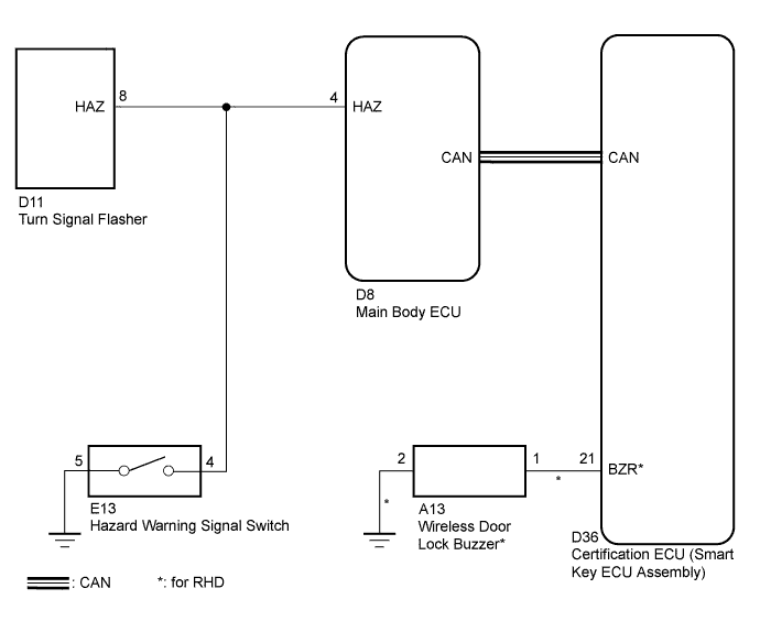
WIRING DIAGRAM
INSPECTION PROCEDURE
PROCEDURE
-
READ VALUE USING INTELLIGENT TESTER (DOOR LOCK POSITION SWITCH)
-
Connect the intelligent tester to the DLC3.
-
Turn the engine switch on (IG).
-
Turn the intelligent tester on.
-
Enter the following menus: Body / Main Body / Data List.
-
Read the Data List according to the display on the intelligent tester.
Main Body (Main Body ECU (Instrument Panel Junction Block)) Tester Display Measurement Item/Range Normal Condition Diagnostic Note D-Door Lock Pos SW Driver door lock position switch signal/LOCK or UNLOCK ON: Driver side door is unlocked
OFF: Driver side door is locked
- P-Door Lock Pos SW Front passenger side door lock position switch signal/ON or OFF ON: Front passenger side door is unlocked
OFF: Front passenger side door is locked
- RR-Door Lock Pos SW Rear right side door lock position switch signal/ON or OFF ON: Rear right side door unlocked
OFF: Rear right side door locked
- RL-Door Lock Pos SW Rear left side door lock position switch signal/ON or OFF ON: Rear left side door unlocked
OFF: Rear left side door locked
- OK On the intelligent tester screen, the display changes between ON and OFF as shown in the chart above. Result Result Proceed to OK A NG (for Driver Side) B
(Proceed to "Driver Door LOCK/UNLOCK Functions do not Operate")
NG (for Front Passenger Side) C
(Proceed to "Front Passenger Door LOCK/UNLOCK Functions do not Operate")
NG (for Rear LH Side) D
(Proceed to "Rear Door LH LOCK/UNLOCK Functions do not Operate")
NG (for Rear RH Side) E
(Proceed to "Rear Door RH LOCK/UNLOCK Functions do not Operate")
B 
GO TO POWER DOOR LOCK CONTROL SYSTEM Click here
C
GO TO POWER DOOR LOCK CONTROL SYSTEM Click here
D
GO TO POWER DOOR LOCK CONTROL SYSTEM Click here
E
GO TO POWER DOOR LOCK CONTROL SYSTEM Click here
A 
-
-
CHECK WIRELESS DOOR LOCK CONTROL FUNCTION
-
Check the wireless door lock control functions by operating the transmitter switch.
Result Result Proceed to Wireless door lock functions are normal but hazard warning lights answer-back does not occur A Wireless door lock functions are normal but wireless door lock buzzer answer-back does not occur* B Doors cannot be locked and unlocked with transmitter C Tech Tips
*: for RHD
B 
PERFORM ACTIVE TEST USING INTELLIGENT TESTER (WIRELESS DOOR LOCK BUZZER) Click here
C
GO TO FLOWCHART Click here
A
-
-
CHECK HAZARD WARNING LIGHT
-
Check that the hazard warning lights flash continuously when the hazard warning signal switch is pressed.
OK Hazard warning lights flash continuously.
NG
GO TO LIGHTING SYSTEM Click here
OK
-
-
PERFORM ACTIVE TEST USING INTELLIGENT TESTER (TURN SIGNAL FLASHER)
-
Select an Active Test, use the intelligent tester to generate a control command, and then check that the hazard warning lights flash.
Main Body ECU Tester Display Test Part Control Range Diagnostic Note Hazard Turn Signal Flasher ON/OFF - OK Hazard warning lights are turned ON/OFF.
NG
REPAIR OR REPLACE HARNESS OR CONNECTOR
OK
-
-
REPLACE MAIN BODY ECU
-
Replace the main body ECU.
NEXT
-
-
CHECK HAZARD WARNING LIGHTS
-
Check that the hazard warning lights flash continuously when the door control transmitter LOCK or UNLOCK switch is pressed.
OK Hazard warning lights flash continuously.
NG
REPLACE CERTIFICATION ECU (SMART KEY ECU ASSEMBLY)
OK 
REPLACE MAIN BODY ECU
-
-
PERFORM ACTIVE TEST USING INTELLIGENT TESTER (WIRELESS DOOR LOCK BUZZER)
-
Select the Active Test, use an intelligent tester to generate a control command, and then check that the wireless buzzer operate normally.
Entry&Start (Certification ECU) Tester Display Test Part Control Range Diagnostic Note Wireless Buzzer wireless buzzer ON/OFF - OK Wireless buzzer turns ON/OFF.
NG
INSPECT WIRELESS DOOR LOCK BUZZER Click here
OK
REPLACE CERTIFICATION ECU (SMART KEY ECU ASSEMBLY)
-
-
INSPECT WIRELESS DOOR LOCK BUZZER
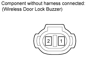
-
Measure the resistance according to the value(s) in the table below.
Standard resistance Tester Connection Condition Specified Condition 1 - 2 Always 950 to 1050 Ω Note
-
The buzzer circuit is built into the certification ECU (smart key ECU assembly), not into the buzzer itself.
-
When battery voltage is directly applied to the buzzer, the buzzer does not sound.
-
NG
REPLACE WIRELESS DOOR LOCK BUZZER Click here
OK
-
-
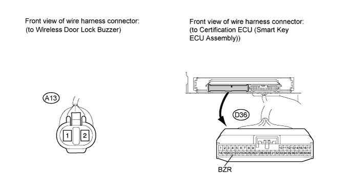
CHECK HARNESS AND CONNECTOR (WIRELESS DOOR LOCK BUZZER - CERTIFICATION ECU AND BODY GROUND)
-
Disconnect the A13 buzzer connector.
-
Disconnect the D36 certification ECU (smart key ECU assembly) connector.
-
Measure the resistance of the wire harness side connectors.
Standard resistance Tester Connection Condition Specified Condition A13-1 - D36-21 (BZR) Always Below 1 Ω A13-2 - Body ground Always Below 1 Ω A13-1 - Body ground Always 10 kΩ or higher
NG
REPAIR OR REPLACE HARNESS OR CONNECTOR
OK
REPLACE CERTIFICATION ECU (SMART KEY ECU ASSEMBLY)
-