WIRELESS DOOR LOCK CONTROL SYSTEM (w/ Smart Entry and Start System) TERMINALS OF ECU
-
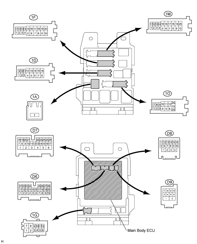
CHECK MAIN BODY ECU (INSTRUMENT PANEL JUNCTION BLOCK)
-
Disconnect the main body ECU (instrument panel junction block) connectors.
-
Measure the resistance and voltage between each terminal of the wire harness side connectors and body ground.
Symbols (Terminal No.) Wiring Color Terminal Description Condition Specified Condition D6-7 (RCTY) - Body ground GR - Body ground Rear courtesy light switch RH input Rear door RH CLOSED (OFF) → OPEN (ON) 10 kΩ or higher → Below 1 Ω D6-21 (PCTY) - Body ground SB - Body ground*1
Passenger side courtesy light switch input Passenger side door CLOSED (OFF) → OPEN (ON) 10 kΩ or higher → Below 1 Ω G - Body ground*2
D6-25 (BCTY) - Body ground L - Body ground Back door courtesy light switch input Back door CLOSED (OFF) → OPEN (ON) 10 kΩ or higher → Below 1 Ω D7-24 (DCTY) - Body ground G - Body ground*1
Driver side door courtesy light switch input Driver side door CLOSED (OFF) → OPEN (ON) 10 kΩ or higher → Below 1 Ω SB - Body ground*2
1A-1 (ACC) - Body ground B - Body ground Ignition power supply (ACC signal) Engine switch on (ACC) → off 10 to 14 V → Below 1 V 1A-1 (IG) - Body ground B - Body ground Ignition power supply (IG signal) Engine switch on (IG) → off 10 to 14 V → Below 1 V 1D-16 (ALTB) - Body ground W - Body ground +B (power system alternator system) power supply Always 10 to 14 V 1F-10 (GND1) - Body ground W-B - Body ground Ground Always Below 1 Ω 1M-9 (GND2) - Body ground W-B - Body ground Ground Always Below 1 Ω 1O-7 (LCTY) - Body ground B - Body ground Rear courtesy light switch LH input Rear door LH CLOSED (OFF) → OPEN (ON) 10 kΩ or higher → Below 1 Ω Tech Tips
-
*1: for LHD
-
*2: for RHD
If the result is not as specified, there may be a malfunction on the wire harness side.
-
-
Reconnect the main body (instrument panel Junction block) connectors.
-
Measure the voltage between each terminal of the wire harness side connectors and body ground.
Symbols (Terminal No.) Wiring Color Terminal Description Condition Specified Condition D7-1 (TR+) - Body ground LG - Body ground*3
Back door opener motor Back door CLOSED (LOCKED) → OPEN (UNLOCKED) Below 1 V → 11 to 14 V*1
D8-4 (HAZ) - Body ground O - Body ground Turn signal flasher relay signal Any transmitter switch is pressed → not pressed Below 1 V → 11 to 14 V*2
Tech Tips
-
*1: When operating the motor.
-
*2: When operating the answer back function.
-
*3: w/o Power Back Door System
-
-
-
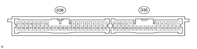
CHECK CERTIFICATION ECU (SMART KEY ECU ASSEMBLY))
-
Disconnect the D36 ECU connector.
-
Measure the resistance and voltage according to the value(s) in the table below.
Terminal No. (Symbols) Wiring Color Terminal Description Condition Specified Condition D36-17 (E) - Body ground B - Body ground Ground Always Below 1 Ω D36-1 (+B) - D36-17 (E) B - B Battery power supply Always 11 to 14 V D36-18 (IG) - D36-17 (E) G - B IG power supply Engine switch on (IG) 11 to 14 V Engine switch off Below 1 V
-
If the result is not as specified, there may be a malfunction on the wire harness side.
-
-
Reconnect the D36 ECU connector.
-
Measure the voltage according to the value(s) in the table below.
Terminal No. (Symbols) Wiring Color Terminal Description Condition Specified Condition D36-39 (RSSI) - D36-17 (E) B - B Door control receiver output signal Engine switch off, all doors closed and transmitter switch not pressed 11 to 14 V Engine switch off, all doors closed and transmitter switch pressed Below 1 V D36-38 (RDA) - D36-17 (E) Y - B Door control receiver output signal Engine switch off, all doors closed and transmitter switch not pressed 4.6 to 5.4 V Engine switch off, all doors closed and transmitter switch pressed Pulse generation D36-29 (RC0) - D36-17 (E) V - B Supply battery to door control receiver Engine switch off, all doors closed and transmitter switch pressed 4.6 to 5.4 V D36-21 (BZR) - Body ground R - Body ground Wireless door lock buzzer signal Wireless door lock buzzer OFF → ON Below 1 V → Pulse generation
-
If the result is not as specified, the ECU may have a malfunction.
-
-