POWER DOOR LOCK CONTROL SYSTEM Key Lock-in Prevention Function does not Work Properly
DESCRIPTION
When the key is in the ignition key cylinder or the door courtesy light ON signal is input to the main body ECU (instrument panel junction block), performing the door lock operation with the lock switch does not lock the door.
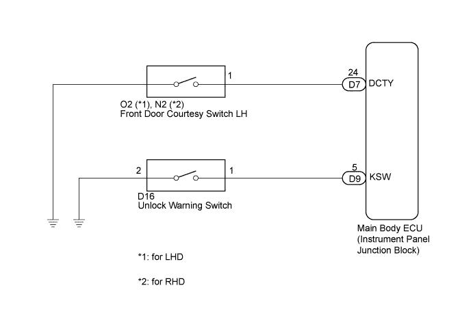
WIRING DIAGRAM
INSPECTION PROCEDURE
PROCEDURE
-
READ VALUE USING INTELLIGENT TESTER (UNLOCK WARNING SWITCH)
-
Connect the intelligent tester to the DLC3.
-
Turn the ignition switch on (IG).
-
Turn the tester on.
-
Select Key Unlock Warning SW in the Data List and read the tester display.
Main Body (Main Body ECU): Tester Display Measurement Item/Range Normal Condition Diagnostic Note Key Unlock Warning SW Unlock warning switch signal/ON or OFF ON: Key is in ignition key cylinder
OFF: No key is in ignition key cylinder
- OK The intelligent tester displays ON or OFF according to whether the key is in the ignition key cylinder.
NG 
INSPECT UNLOCK WARNING SWITCH ASSEMBLY Click here
OK 
-
-
READ VALUE USING INTELLIGENT TESTER (DRIVER SIDE DOOR COURTESY LIGHT SWITCH)
-
Connect the intelligent tester to the DLC3.
-
Turn the ignition switch on (IG).
-
Turn the tester on.
-
Select D Door Courtesy SW in the Data List and read the tester display.
Main Body (Main Body ECU): Tester Display Measurement Item/Range Normal Condition Diagnostic Note D Door Courtesy SW Driver side door courtesy light switch signal/ON or OFF ON: Driver side door is open
OFF: Driver side door is closed
- OK The intelligent tester displays ON or OFF according to whether the driver side door is open or closed.
NG
INSPECT FRONT DOOR COURTESY LIGHT SWITCH ASSEMBLY Click here
OK 
REPLACE MAIN BODY ECU (INSTRUMENT PANEL JUNCTION BLOCK)
-
-
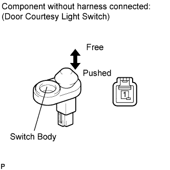
INSPECT FRONT DOOR COURTESY LIGHT SWITCH ASSEMBLY
-
Remove the driver side door courtesy light switch Click here.
-
Measure the resistance according to the value(s) in the table below.
Standard resistance Tester Connection Condition Specified Condition 1 - Switch ground Not pushed (ON) Below 1 Ω 1 - Switch ground Pushed (OFF) 10 kΩ or higher
NG 
REPLACE FRONT DOOR COURTESY LIGHT SWITCH ASSEMBLY Click here
OK
-
-
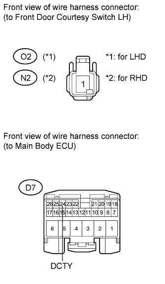
CHECK HARNESS AND CONNECTOR (FRONT DOOR COURTESY SWITCH CIRCUIT)
-
Disconnect the main body ECU (instrument panel junction block) connector.
-
Measure the resistance according to the value(s) in the table below.
Standard resistance for LHD Tester Connection Condition Specified Condition O2-1 - D7-24 (DCTY) Always Below 1 Ω O2-1 - Body ground Always 10 kΩ or higher for RHD Tester Connection Condition Specified Condition N2-1 - D7-24 (DCTY) Always Below 1 Ω N2-1 - Body ground Always 10 kΩ or higher
NG
REPAIR OR REPLACE HARNESS OR CONNECTOR
OK
REPLACE MAIN BODY ECU (INSTRUMENT PANEL JUNCTION BLOCK)
-
-
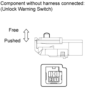
INSPECT UNLOCK WARNING SWITCH ASSEMBLY
-
Remove the unlock warning switch Click here.
-
Measure the resistance according to the value(s) in the table below.
Standard resistance Tester Connection Switch Condition Specified Condition 1 - 2 Pushed Below 1 Ω 1 - 2 Not pushed 10 kΩ or higher
NG
REPLACE UNLOCK WARNING SWITCH ASSEMBLY Click here
OK
-
-
CHECK HARNESS AND CONNECTOR (UNLOCK WARNING SWITCH CIRCUIT)
-
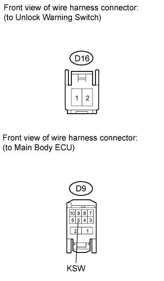
Disconnect the main body ECU (instrument panel junction block) connector.
-
Measure the resistance according to the value(s) in the table below.
Standard resistance Tester Connection Condition Specified Condition D16-1 - D9-5 (KSW) Always Below 1 Ω D16-1 - Body ground Always 10 kΩ or higher D16-2 - Body ground Always Below 1 Ω
NG
REPAIR OR REPLACE HARNESS OR CONNECTOR
OK
REPLACE MAIN BODY ECU (INSTRUMENT PANEL JUNCTION BLOCK)
-