POWER DOOR LOCK CONTROL SYSTEM Only Back Door LOCK / UNLOCK Functions do not Operate
DESCRIPTION
-
The main body ECU (instrument panel junction block) detects the condition of the back door opener switch.
-
The main body ECU (instrument panel junction block) receives signals from the back door opener switch and activates the back door lock motor according to the signals.
-
The main body ECU (instrument panel junction block) detects the condition of the back door courtesy switch.
WIRING DIAGRAM

INSPECTION PROCEDURE
PROCEDURE
-
SYSTEM CHECK
-
Check if the vehicle is equipped with a back door closer system.
Result Result Proceed to w/ Back Door Closer System A w/o Back Door Closer System B
A 
GO TO BACK DOOR CLOSER SYSTEM (Back Door cannot be Opened) Click here
B 
-
-
READ VALUE USING INTELLIGENT TESTER (BACK DOOR OPENER SWITCH)
-
Connect the intelligent tester to the DLC3.
-
Turn the ignition switch on (IG).
-
Turn the tester on.
-
Select Back Door Open Handle in the Data List and read the tester display.
Main Body (Main Body ECU): Tester Display Measurement Item/Range Normal Condition Diagnostic Note Back Door Open Handle Back door opener switch/ON or OFF ON: Back door opener switch is pushed
OFF: Back door opener switch is not pushed
- OK On the tester screen, the item changes between ON and OFF according to the chart above.
NG 
INSPECT BACK DOOR OPENER SWITCH Click here
OK
-
-
INSPECT BACK DOOR LOCK ASSEMBLY
-
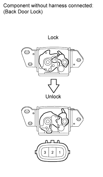
Remove the back door lock assembly Click here.
-
Check operation of the door lock motor.
-
Move the door lock to the lock position.
-
Apply battery voltage to the door lock motor and check the operation of the door lock motor.
OK Measurement Condition Specified Condition Battery positive (+) → Terminal 2
Battery negative (-) → Terminal 1
Unlocked
-
-
Check operation of the door courtesy switch.
-
Measure the resistance according to the value(s) in the table below.
Standard resistance Tester Connection Switch Condition Specified Condition 1 - 3 Locked 10 kΩ or higher 1 - 3 Unlocked Below 1 Ω
-
NG
REPLACE BACK DOOR LOCK ASSEMBLY Click here
OK
-
-
CHECK HARNESS AND CONNECTOR (BACK DOOR LOCK CIRCUIT)
-
Disconnect the main body ECU (instrument panel junction block) connector.
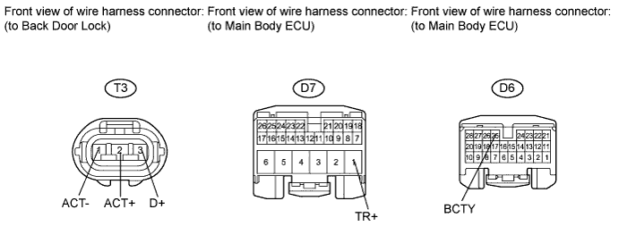
-
Measure the resistance according to the value(s) in the table below.
Standard resistance Tester Connection Condition Specified Condition T3-2 (ACT+) - D7-1 (TR+) Always Below 1 Ω T3-2 (ACT+) - Body ground Always 10 kΩ or higher T3-3 (D+) - D6-25 (BCTY) Always Below 1 Ω T3-3 (D+) - Body ground Always 10 kΩ or higher T3-1 (ACT-) - Body ground Always Below 1 Ω
NG
REPAIR OR REPLACE HARNESS OR CONNECTOR
OK 
REPLACE MAIN BODY ECU (INSTRUMENT PANEL JUNCTION BLOCK)
-
-
INSPECT BACK DOOR OPENER SWITCH
-
Remove the back door opener switch Click here.
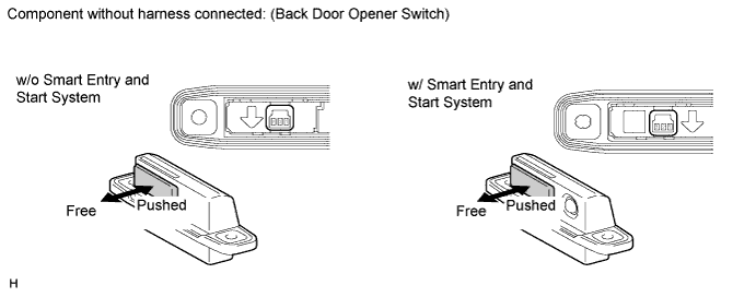
-
Measure the resistance according to the value(s) in the table below.
Standard resistance Tester Connection Switch Position Specified Condition 2 - 3 Back door opener switch not pushed (OFF) 10 kΩ or higher 2 - 3 Back door opener switch pushed (ON) Below 1 Ω
NG
REPLACE BACK DOOR OPENER SWITCH Click here
OK
-
-
CHECK HARNESS AND CONNECTOR (BACK DOOR OPENER SWITCH CIRCUIT)
-
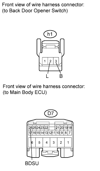
Disconnect the main body ECU (instrument panel junction block) connector.
-
Measure the resistance according to the value(s) in the table below.
Standard resistance Tester Connection Condition Specified Condition h1-3 (B) - D7-26 (BDSU) Always Below 1 Ω h1-3 (B) - Body ground Always 10 kΩ or higher h1-2 (L) - Body ground Always Below 1 Ω
NG
REPAIR OR REPLACE HARNESS OR CONNECTOR
OK
REPLACE MAIN BODY ECU (INSTRUMENT PANEL JUNCTION BLOCK)
-