POWER DOOR LOCK CONTROL SYSTEM Only Driver Door LOCK / UNLOCK Functions do not Operate
DESCRIPTION
The main body ECU (instrument panel junction block) receives lock/unlock switch signals and activates the door lock motor according to these signals.
WIRING DIAGRAM
INSPECTION PROCEDURE
PROCEDURE
-
INSPECT FRONT DOOR LOCK ASSEMBLY
-
Remove the front driver side door lock assembly Click here.
-
Measure the resistance according to the value(s) in the table below.
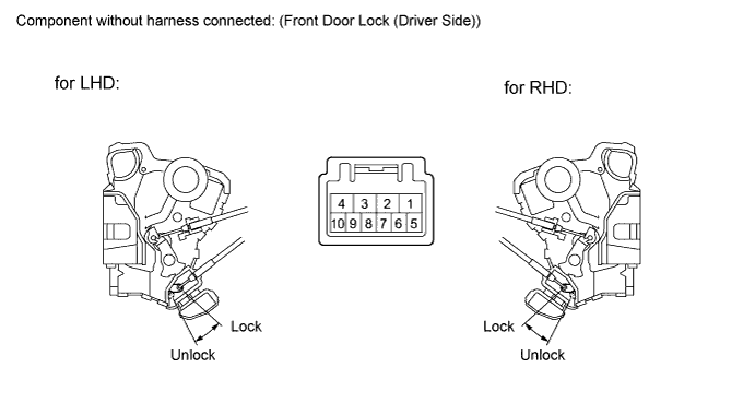
Standard resistance Tester Connection Measurement Condition Door Lock Condition Specified Condition 7 - 8 Battery positive (+) → Terminal 4
Battery negative (-) → Terminal 1
Locked 10 kΩ or higher 7 - 8 Battery positive (+) → Terminal 1
Battery negative (-) → Terminal 4
Unlocked Below 1 Ω
NG 
REPLACE FRONT DOOR LOCK ASSEMBLY Click here
OK 
-
-
CHECK HARNESS AND CONNECTOR (FRONT DOOR LOCK MOTOR CIRCUIT)
-
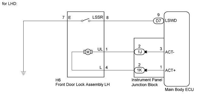
for LHD:
-
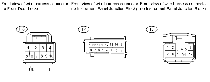
Disconnect the instrument panel junction block connector.
-
Measure the resistance according to the value(s) in the table below.
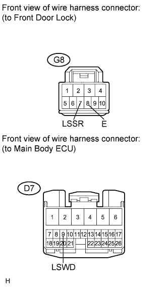
Standard resistance Tester Connection Condition Specified Condition H6-1 (UL) - 1J-2 Always Below 1 Ω H6-4 (L) - 1K-2 Always Below 1 Ω H6-1 (UL) - Body ground Always 10 kΩ or higher H6-4 (L) - Body ground Always 10 kΩ or higher
-
-
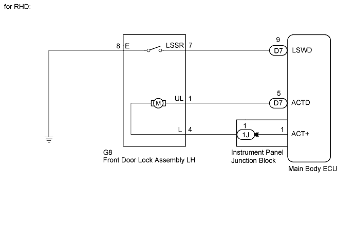
for RHD:
-
Disconnect the main body ECU (instrument panel junction block) connector.
-
Disconnect the instrument panel junction block connector.
-
Measure the resistance according to the value(s) in the table below.
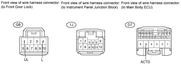
Standard resistance Tester Connection Condition Specified Condition G8-1 (UL) - D7-5 (ACTD) Always Below 1 Ω G8-4 (L) - 1J-1 Always Below 1 Ω G8-1 (UL) - Body ground Always 10 kΩ or higher G8-4 (L) - Body ground Always 10 kΩ or higher
-
NG
REPAIR OR REPLACE HARNESS OR CONNECTOR
OK
-
-
CHECK HARNESS AND CONNECTOR (DOOR UNLOCK DETECTION SWITCH CIRCUIT)
-
for LHD:
-
Measure the resistance according to the value(s) in the table below.
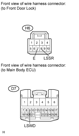
Standard resistance Tester Connection Condition Specified Condition H6-8 (LSSR) - D7-9 (LSWD) Always Below 1 Ω H6-8 (LSSR) - Body ground Always 10 kΩ or higher H6-7 (E) - Body ground Always Below 1 Ω
-
-
for RHD:
-
Measure the resistance according to the value(s) in the table below.
Standard resistance Tester Connection Condition Specified Condition G8-7 (LSSR) - D7-9 (LSWD) Always Below 1 Ω G8-7 (LSSR) - Body ground Always 10 kΩ or higher G8-8 (E) - Body ground Always Below 1 Ω
-
NG
REPAIR OR REPLACE HARNESS OR CONNECTOR
OK 
REPLACE MAIN BODY ECU (INSTRUMENT PANEL JUNCTION BLOCK)
-