POWER DOOR LOCK CONTROL SYSTEM All Doors LOCK/UNLOCK Functions do not Operate Via Door Control Switch
DESCRIPTION
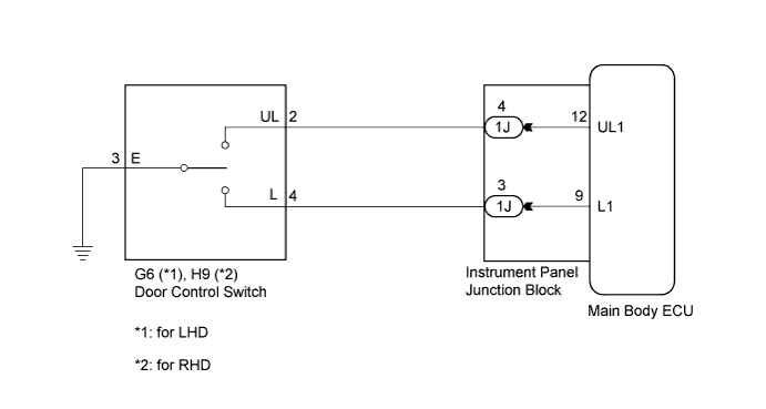
The main body ECU (instrument panel junction block) receives switch signals from the door control switch and activates the door lock motor on each door according to these signals.
WIRING DIAGRAM
INSPECTION PROCEDURE
PROCEDURE
-
INSPECT DOOR CONTROL SWITCH ASSEMBLY (DOOR LOCK AND UNLOCK SWITCH)
-
Remove the door control switch Click here.
-
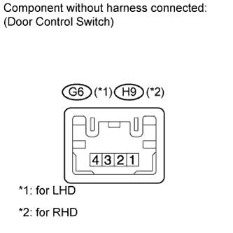
Measure the resistance according to the value(s) in the table below.
Standard resistance Tester Connection Switch Condition Specified Condition 4 - 3 Locked Below 1 Ω 4 - 3
2 - 3
OFF (Free) 10 kΩ or higher 2 - 3 Unlocked Below 1 Ω
NG 
REPLACE DOOR CONTROL SWITCH ASSEMBLY Click here
OK 
-
-
CHECK HARNESS AND CONNECTOR (DOOR CONTROL SWITCH CIRCUIT)
-
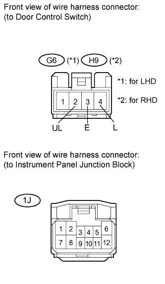
Disconnect the instrument panel junction block connector.
-
Measure the resistance according to the value(s) in the table below.
Standard resistance for LHD Tester Connection Condition Specified Condition G6-2 (UL) - 1J-4 Always Below 1 Ω G6-4 (L) - 1J-3 Always Below 1 Ω G6-3 (E) - Body ground Always Below 1 Ω G6-2 (UL) - Body ground Always 10 kΩ or higher G6-4 (L) - Body ground Always 10 kΩ or higher for RHD Tester Connection Condition Specified Condition H9-2 (UL) - 1J-4 Always Below 1 Ω H9-4 (L) - 1J-3 Always Below 1 Ω H9-3 (E) - Body ground Always Below 1 Ω H9-2 (UL) - Body ground Always 10 kΩ or higher H9-4 (L) - Body ground Always 10 kΩ or higher
NG
REPAIR OR REPLACE HARNESS OR CONNECTOR
OK 
REPLACE MAIN BODY ECU (INSTRUMENT PANEL JUNCTION BLOCK)
-