STOP LIGHT SWITCH INSTALLATION
-
INSTALL STOP LIGHT SWITCH ASSEMBLY
-
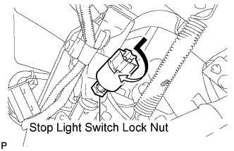
Temporarily install the stop light switch assembly with the stop light switch lock nut.
-
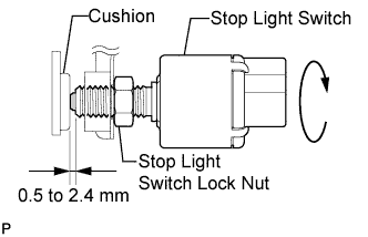
Turn the stop light switch assembly so that the clearance between the nut end and stop light switch cushion is between 0.5 to 2.4 mm (0.020 to 0.095 in.).
-
Tighten the stop light switch lock nut.
- Torque:
- 17 N*m { 173 kgf*cm, 12 ft.*lbf }
-
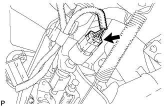
Connect the connector.
-
-
INSTALL LOWER INSTRUMENT PANEL FINISH PANEL SUB-ASSEMBLY (for Manual Air Conditioning System)
-

Connect the hood lock control cable assembly.
-
Connect each connector.
-
Engage the 3 claws and 10 clips.
-
Install the lower instrument panel finish panel sub-assembly with the 2 bolts <B>.
-
-
INSTALL LOWER INSTRUMENT PANEL FINISH PANEL SUB-ASSEMBLY (for Automatic Air Conditioning System)
-

Connect the hood lock control cable assembly.
-
Connect each connector and the aspirator duct.
-

Engage the 3 claws and 10 clips.
-
Install the lower instrument panel finish panel sub-assembly with the 2 bolts <B>.
-
-
INSTALL COWL SIDE TRIM SUB-ASSEMBLY LH
-

Engage the claw and clip, install the cowl side trim sub-assembly LH.
-
Install the clip.
-
-
INSTALL FRONT DOOR SCUFF PLATE LH
-

Engage the guide and the 8 claws, and install the front door scuff plate LH.
-