Click here
- Click here
INSPECT REAR COMBINATION LIGHT ASSEMBLY
-
Disconnect the connectors from the rear combination light assembly.
-
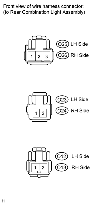
Measure the voltage according to the value(s) in the table below.
Standard voltage LH Side Tester Connection Condition Specified Condition O25-1 - O25-2 Light control switch OFF Below 1 V Light control switch in TAIL 11 to 14 V O25-1 - O25-3 Brake pedal released Below 1 V Brake pedal depressed 11 to 14 V O23-1 - O23-2 Turn signal switch OFF Below 1 V Ignition switch on (IG) and Turn signal switch in LH 11 to 14 V (60 to 120 times per minute) O12-1 - O12-2 Shift lever not in R Below 1 V Shift lever in R 11 to 14 V RH Side Tester Connection Condition Specified Condition O26-1 - O26-2 Light control switch OFF Below 1 V Light control switch in TAIL 11 to 14 V O26-1 - O26-3 Brake pedal released Below 1 V Brake pedal depressed 11 to 14 V O24-1 - O24-2 Turn signal switch OFF Below 1 V Ignition switch on (IG) and Turn signal switch in LH 11 to 14 V (60 to 120 times per minute) O13-1 - O13-2 Shift lever not in R Below 1 V Shift lever in R 11 to 14 V If the result is not as specified, there is a malfunction on the wire harness side.
-