LIGHTING SYSTEM Interior Light Circuit
DESCRIPTION
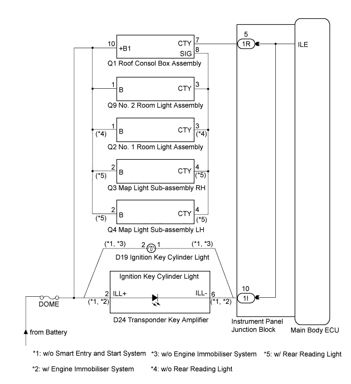
The illuminated entry system controls the personal light, interior lights and ignition key cylinder light*1.
Tech Tips
*1: w/o Smart Entry and Start System
WIRING DIAGRAM
INSPECTION PROCEDURE
PROCEDURE
-
PERFORM ACTIVE TEST USING INTELLIGENT TESTER
-
Connect the intelligent tester to the DLC3.
-
Turn the ignition switch on (IG).
-
Turn the intelligent tester on.
-
Select the following menu items: Body Electrical / Main Body / Active Test.
-
Check the operation.
Main Body: Tester Display Test Part Control Range Diagnostic Note Illuminated Entry System Personal light, interior lights and ignition key cylinder light (Light switch is in DOOR position and all doors are closed). ON/OFF - OK Each light fades in.
NG 
INSPECT FUSE (DOME) Click here
OK 
PROCEED TO NEXT CIRCUIT INSPECTION SHOWN IN PROBLEM SYMPTOMS TABLE Click here
-
-
INSPECT FUSE (DOME)
-
Remove the DOME fuse from the engine room relay block.
-
Measure the resistance according to the value(s) in the table below.
Standard resistance Tester Display Condition Specified Condition DOME fuse Always Below 1 Ω
NG 
REPLACE FUSE
OK 
-
-
CHECK HARNESS AND CONNECTOR (BATTERY - INSTRUMENT PANEL JUNCTION BLOCK)
-
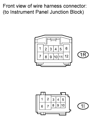
Disconnect the 1I and 1R instrument panel junction block connectors.
-
Measure the voltage according to the value(s) in the table below.
Standard voltage Tester Connection Condition Specified Condition 1I-10 (ILE) - Body ground Always 11 to 14 V 1R-5 (ILE) - Body ground Always 11 to 14 V
NG
REPAIR OR REPLACE HARNESS OR CONNECTOR
OK
REPLACE MAIN BODY ECU (INSTRUMENT PANEL JUNCTION BLOCK)
-