LIGHTING SYSTEM Door LOCK Position Circuit
DESCRIPTION
The main body ECU receives each door lock position switch signal to control the illuminated entry system.
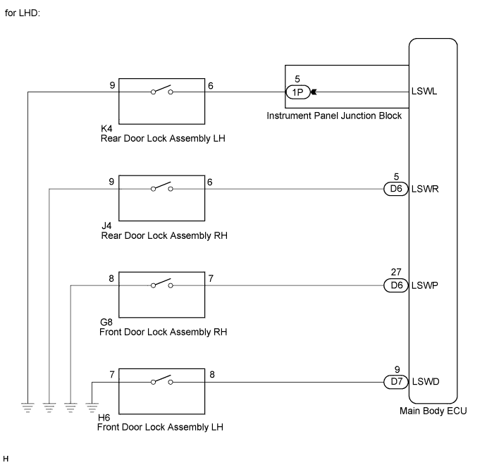
WIRING DIAGRAM

INSPECTION PROCEDURE
PROCEDURE
-
READ VALUE USING INTELLIGENT TESTER
-
Connect the intelligent tester to the DLC3.
-
Turn the ignition switch on (IG).
-
Turn the intelligent tester on.
-
Select the following menu items: Body Electrical / Main Body / Data List.
-
Read the display on the intelligent tester.
Main Body: Tester Display Measurement Item/Range Normal Condition Diagnostic Note D-Door Lock Pos SW Driver side door lock position switch signal / ON or OFF ON: Driver side door unlocked
OFF: Driver side door locked
- P-Door Lock Pos SW Front passenger side door lock position switch signal / ON or OFF ON: Front passenger side door unlocked
OFF: Front passenger side locked
- RL-Door Lock Pos SW Rear door lock position switch LH signal / ON or OFF ON: Rear door LH unlocked
OFF: Rear door LH locked
- RR-Door Lock Pos SW Rear door lock position switch RH signal / ON or OFF ON: Rear door RH unlocked
OFF: Rear door RH locked
- OK Normal conditions listed above are displayed. Tech Tips
If the normal condition listed above are not displayed, perform the trouble shooting of the power door lock control system.
NG 
GO TO POWER DOOR LOCK CONTROL SYSTEM
OK 
PROCEED TO NEXT CIRCUIT INSPECTION SHOWN IN PROBLEM SYMPTOMS TABLE Click here
-