| DTC Code | DTC Name |
|---|---|
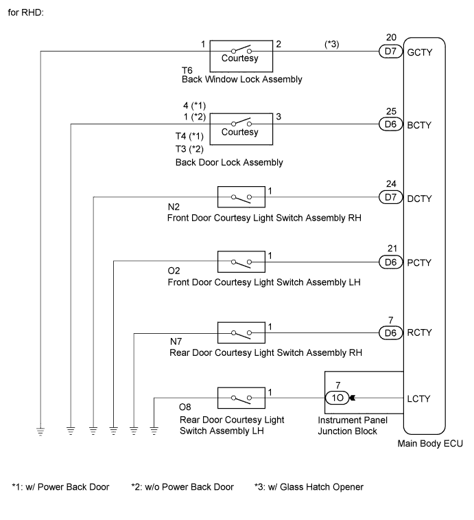
| Door Courtesy Switch Circuit |
DESCRIPTION
The main body ECU receives courtesy switch signals to control the illuminated entry system and light auto turn off system.
INSPECTION PROCEDURE
PROCEDURE
- Click here
READ VALUE USING INTELLIGENT TESTER
-
Connect the intelligent tester to the DLC3.
-
Turn the ignition switch on (IG).
-
Turn the intelligent tester on.
-
Select the following menu items: Body Electrical / Main Body / Data List.
-
Read the display on the intelligent tester.
Table 1. Main Body: Tester Display Measurement Item/Range Normal Condition Diagnostic Note D door Courtesy SW Driver side door courtesy switch signal / ON or OFF ON: Driver side door open
OFF: Driver side door closed
- P door Courtesy SW Front passenger side door courtesy switch signal / ON or OFF ON: Front passenger side door open
OFF: Front passenger side door closed
- RR door Courtesy SW Rear door courtesy switch RH signal / ON or OFF ON: Rear door RH open
OFF: Rear door RH closed
- RL door Courtesy SW Rear door courtesy switch LH signal / ON or OFF ON: Rear door LH open
OFF: Rear door LH closed
- Back door Courtesy SW Back door Courtesy switch signal / ON or OFF ON: Back door open
OFF: Back door closed
- Glass Hatch Courtesy Switch Back window Courtesy Switch signal / ON or OFF ON: Back window open
OFF: Back window closed
- OK Normal conditions listed above are displayed.
- OKClick here
- NGClick here
-
- Click here
INSPECT COURTESY SWITCH
-
Inspect the front door courtesy switches (Click here).
-
Inspect the rear door courtesy switches (Click here).
-
Inspect the back door courtesy switch (Click here).
-
Inspect the back window courtesy switch (Click here).
OK Courtesy switches are normal.
- OKClick here
- NGClick here
-
- Click here
CHECK HARNESS AND CONNECTOR (MAIN BODY ECU - COURTESY SWITCH)
-
Check the harness and connector between the main body ECU and front door courtesy switch LH (for LHD).
-
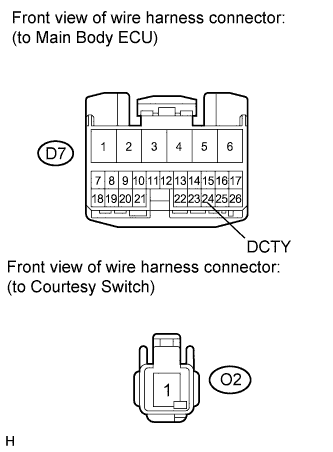
Disconnect the D7 main body ECU connector.
-
Disconnect the O2 switch connector.
-
Measure the resistance according to the value(s) in the table below.
Standard resistance Tester Connection Condition Specified Condition D7-24 (DCTY) - O2-1 Always Below 1 Ω D7-24 (DCTY) - Body ground Always 10 kΩ or higher
-
-

Check the harness and connector between the main body ECU and front door courtesy switch LH (for RHD).
-
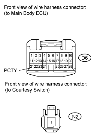
Disconnect the D6 main body ECU connector.
-
Disconnect the O2 switch connector.
-
Measure the resistance according to the value(s) in the table below.
Standard resistance Tester Connection Condition Specified Condition D6-21 (PCTY) - O2-1 Always Below 1 Ω D6-21 (PCTY) - Body ground Always 10 kΩ or higher
-
-
Check the harness and connector between the main body ECU and front door courtesy switch RH (for LHD).
-
Disconnect the D6 main body ECU connector.
-
Disconnect the N2 switch connector.
-
Measure the resistance according to the value(s) in the table below.
Standard resistance Tester Connection Condition Specified Condition D6-21 (PCTY) - N2-1 Always Below 1 Ω D6-21 (PCTY) - Body ground Always 10 kΩ or higher
-
-

Check the harness and connector between the main body ECU and front door courtesy switch RH (for RHD).
-
Disconnect the D7 main body ECU connector.
-
Disconnect the N2 switch connector.
-
Measure the resistance according to the value(s) in the table below.
Standard resistance Tester Connection Condition Specified Condition D7-24 (DCTY) - N2-1 Always Below 1 Ω D7-24 (DCTY) - Body ground Always 10 kΩ or higher
-
-
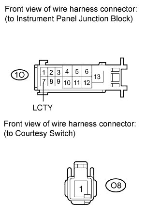
Check the harness and connector between the instrument panel junction block and rear door courtesy switch LH.
-
Disconnect the 1O instrument panel junction block connector.
-
Disconnect the O8 switch connector.
-
Measure the resistance according to the value(s) in the table below.
Standard resistance Tester Connection Condition Specified Condition 1O-7 (LCTY) - O8-1 Always Below 1 Ω 1O-7 (LCTY) - Body ground Always 10 kΩ or higher
-
-
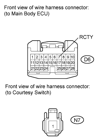
Check the harness and connector between the main body ECU and rear door courtesy switch RH.
-
Disconnect the D6 main body ECU connector.
-
Disconnect the N7 switch connector.
-
Measure the resistance according to the value(s) in the table below.
Standard resistance Tester Connection Condition Specified Condition D6-7 (RCTY) - N7-1 Always Below 1 Ω D6-7 (RCTY) - Body ground Always 10 kΩ or higher
-
-
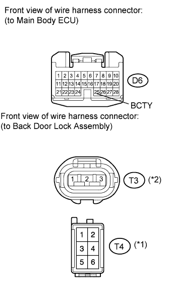
Check the harness and connector between the main body ECU and back door lock assembly.
-
Disconnect the D6 main body ECU connector.
-
Disconnect the T4*1 or T3*2 back door lock assembly connector.
-
Measure the resistance according to the value(s) in the table below.
Standard resistance Tester Connection Condition Specified Condition D6-25 (BCTY) - T4-3*1
Always Below 1 Ω D6-25 (BCTY) - T3-3*2
Always Below 1 Ω D6-25 (BCTY) - Body ground Always 10 kΩ or higher *1: w/ Power Back Door
*2: w/o Power Back Door
-
-
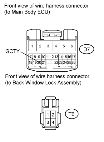
Check the harness and connector between the main body ECU and back window lock assembly (w/ Glass Hatch Opener).
-
Disconnect the D7 main body ECU connector.
-
Disconnect the T6 back window lock assembly connector.
-
Measure the resistance according to the value(s) in the table below.
Standard resistance Tester Connection Condition Specified Condition D7-20 (GCTY) - T6-2 Always Below 1 Ω D7-20 (GCTY) - Body ground Always 10 kΩ or higher
-
- OKClick here
- NGClick here
-
- Click here
REPLACE COURTESY SWITCH
- Click here
REPAIR OR REPLACE HARNESS OR CONNECTOR
- Click here
PROCEED TO NEXT CIRCUIT INSPECTION SHOWN IN PROBLEM SYMPTOMS TABLEClick here
- Click here
REPLACE MAIN BODY ECU (INSTRUMENT PANEL JUNCTION BLOCK)