LIGHTING SYSTEM Light Control Switch Circuit
DESCRIPTION
The main body ECU receives the following signals:
-
Light control switch TAIL, HEAD, or AUTO signal
-
Dimmer switch HIGH or HIGH FLASH (PASS) signal
-
Front fog light switch signal
-
Rear fog light switch signal
Tech Tips
When performing troubleshooting, inspect the switch that is related to the malfunction. For example, if both right and left low beam headlights do not illuminate, read the light control switch HEAD signal value only in the data list. If the value is normal, perform the headlight relay active test.
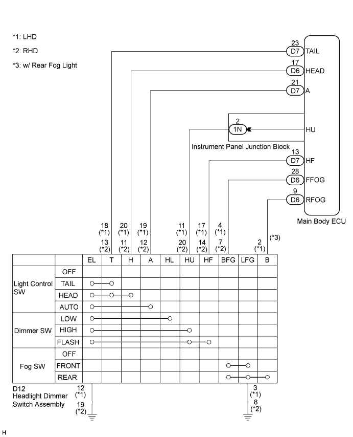
WIRING DIAGRAM
INSPECTION PROCEDURE
PROCEDURE
-
READ VALUE USING INTELLIGENT TESTER
-
Connect the intelligent tester to the DLC3.
-
Turn the ignition switch on (IG).
-
Turn the intelligent tester on.
-
Select the following menu items: Body Electrical / Main Body / Data List.
-
Read the displays on the intelligent tester.
Main Body: Tester Display Measurement Item/Range Normal Condition Diagnostic Note Dimmer Hi SW Dimmer switch HIGH signal / ON or OFF ON: Dimmer switch in HIGH
OFF: Dimmer switch in LOW
- Passing Light SW Dimmer switch FLASH signal / ON or OFF ON: Dimmer switch in HIGH FLASH (PASS)
OFF: Dimmer switch not in HIGH FLASH (PASS)
- Front Fog Light SW Front fog light switch signal / ON or OFF ON: Front fog light switch ON
OFF: Front fog light switch OFF
- Rear Fog Light SW Rear fog light switch signal / ON or OFF ON: Rear fog light switch ON
OFF: Rear fog light switch OFF
- Light Auto SW Light control switch AUTO signal / ON or OFF ON: Light control switch in AUTO
OFF: Light control switch not in AUTO
- Headlight SW Light control switch HEAD signal / ON or OFF ON: Light control switch in HEAD
OFF: Light control switch not in HEAD
- Taillight SW Light control switch TAIL signal / ON or OFF ON: Light control switch in TAIL or HEAD
OFF: Light control switch in neither TAIL nor HEAD
- OK Normal conditions listed above are displayed.
NG 
INSPECT HEADLIGHT DIMMER SWITCH ASSEMBLY Click here
OK 
PROCEED TO NEXT CIRCUIT INSPECTION SHOWN IN PROBLEM SYMPTOMS TABLE Click here
-
-
INSPECT HEADLIGHT DIMMER SWITCH ASSEMBLY
-
Inspect the headlight dimmer switch assembly Click here.
OK Headlight dimmer switch assembly is normal.
NG 
REPLACE HEADLIGHT DIMMER SWITCH ASSEMBLY
OK 
-
-
CHECK HARNESS AND CONNECTOR (SWITCH - INSTRUMENT PANEL J/B AND BODY GROUND)
-
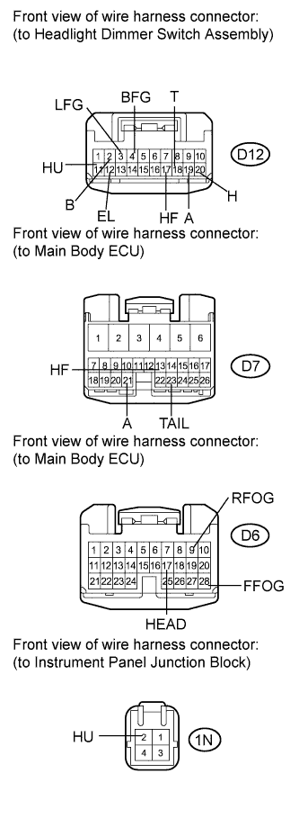
for LHD:
-
Disconnect the D12 headlight dimmer switch assembly connector.
-
Disconnect the D6 and D7 main body ECU connectors.
-
Disconnect the 1N instrument panel junction block connector.
-
Measure the resistance according to the value(s) in the table below.
Standard resistance Tester Connection Condition Specified Condition D12-2 (B) - D6-9 (RFOG) Always Below 1 Ω D12-4 (BFG) - D6-28 (FFOG) Always Below 1 Ω D12-11 (HU) - 1N-2 (HU) Always Below 1 Ω D12-17 (HF) - D7-13 (HF) Always Below 1 Ω D12-18 (T) - D7-23 (TAIL) Always Below 1 Ω D12-19 (A) - D7-21 (A) Always Below 1 Ω D12-20 (H) - D6-17 (HEAD) Always Below 1 Ω D12-2 (B) - Body ground Always 10 kΩ or higher D12-3 (LFG) - Body ground Always 10 kΩ or higher D12-4 (BFG) - Body ground Always 10 kΩ or higher D12-11 (HU) - Body ground Always 10 kΩ or higher D12-17 (HF) - Body ground Always 10 kΩ or higher D12-18 (T) - Body ground Always 10 kΩ or higher D12-19 (A) - Body ground Always 10 kΩ or higher D12-20 (H) - Body ground Always 10 kΩ or higher D12-12 (EL) - Body ground Always Below 1 Ω D12-3 (LFG) - Body ground Always Below 1 Ω
-
-
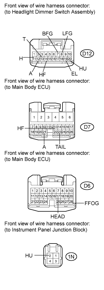
for RHD:
-
Disconnect the D12 headlight dimmer switch assembly connector.
-
Disconnect the D6 and D7 main body ECU connectors.
-
Disconnect the 1N instrument panel junction block connector.
-
Measure the resistance according to the value(s) in the table below.
Standard resistance Tester Connection Condition Specified Condition D12-13 (T) - D7-23 (TAIL) Always Below 1 Ω D12-7 (BFG) - D6-28 (FFOG) Always Below 1 Ω D12-11 (H) - D6-17 (HEAD) Always Below 1 Ω D12-12 (A) - D7-21 (A) Always Below 1 Ω D12-14 (HF) - D7-13 (HF) Always Below 1 Ω D12-20 (HU) - 1N-2 (HU) Always Below 1 Ω D12-13 (T) - Body ground Always 10 kΩ or higher D12-7 (BFG) - Body ground Always 10 kΩ or higher D12-11 (H) - Body ground Always 10 kΩ or higher D12-12 (A) - Body ground Always 10 kΩ or higher D12-14 (HF) - Body ground Always 10 kΩ or higher D12-20 (HU) - Body ground Always 10 kΩ or higher D12-19 (EL) - Body ground Always Below 1 Ω D12-8 (LFG) - Body ground Always Below 1 Ω
-
NG
REPAIR OR REPLACE HARNESS OR CONNECTOR
OK
REPLACE MAIN BODY ECU (INSTRUMENT PANEL JUNCTION BLOCK)
-