LIGHTING SYSTEM Front Fog Light Circuit
DESCRIPTION
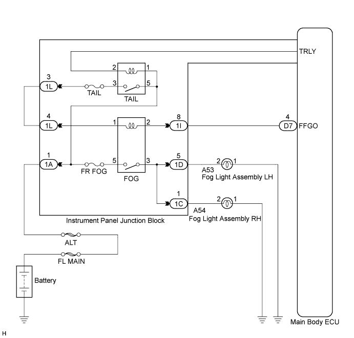
The main body ECU controls the front fog light relay when a signal is received from the headlight dimmer switch assembly.
WIRING DIAGRAM
INSPECTION PROCEDURE
PROCEDURE
-
PERFORM ACTIVE TEST USING INTELLIGENT TESTER
-
Connect the intelligent tester to the DLC3.
-
Turn the ignition switch on (IG).
-
Turn the intelligent tester on.
-
Select the following menu items: Body Electrical / Main Body / Active Test.
-
Check that the relay operates.
Main Body: Tester Display Test Part Control Range Diagnostic Note Front Fog Light Relay Front fog light relay ON/OFF - OK Front fog light relay operates. (Front fog lights come on.)
NG 
INSPECT FUSE (FR FOG) Click here
OK 
PROCEED TO NEXT CIRCUIT INSPECTION SHOWN IN PROBLEM SYMPTOMS TABLE Click here
-
-
INSPECT FUSE (FR FOG)
-
Remove the FR FOG fuse from the instrument panel junction block.
-
Measure the resistance according to the value(s) in the table below.
Standard resistance Tester Connection Condition Specified Condition FR FOG fuse Always Below 1 Ω
NG 
REPLACE FUSE
OK 
-
-
INSPECT FOG LIGHT RELAY (FOG)
-
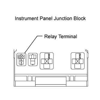
Remove the front fog light relay from the instrument panel junction block.
-
Measure the resistance according to the value(s) in the table below.
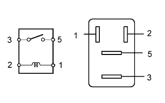
Standard resistance Tester Connection Condition Specified Condition 3 - 5 Voltage is not applied between terminals 1 and 2 10 kΩ or higher 3 - 5 Apply the battery voltage between terminals 1 and 2 Below 1 Ω
NG
REPLACE FOG LIGHT RELAY
OK
-
-
CHECK HARNESS AND CONNECTOR (BATTERY - FRONT FOG LIGHT RELAY)
-
Measure the voltage according to the value(s) in the table below.
Standard voltage Tester Connection Condition Specified Condition Front fog light relay terminal 5 - Body ground Always 11 to 14 V Front fog light relay terminal 1 - Body ground Light control switch OFF → TAIL Below 1 V → 11 to 14 V
NG
REPAIR OR REPLACE HARNESS OR CONNECTOR
OK
-
-
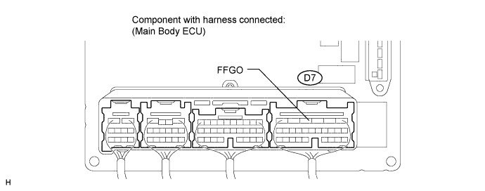
CHECK HARNESS AND CONNECTOR (FRONT FOG LIGHT RELAY - MAIN BODY ECU)
-
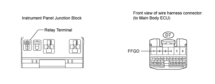
Disconnect the D7 main body ECU connector.
-
Measure the resistance according to the value(s) in the table below.
Standard resistance Tester Connection Condition Specified Condition Front fog light relay terminal 2 - D7-4 (FFGO) Always Below 1 Ω D7-4 (FFGO) - Body ground Always 10 kΩ or higher
NG
REPAIR OR REPLACE HARNESS OR CONNECTOR
OK
-
-
INSPECT MAIN BODY ECU (INSTRUMENT PANEL JUNCTION BLOCK)
-
Reconnect the D7 main body ECU connector.
-
Install the front fog light relay to the instrument panel junction block.
-
Measure the voltage according to the value(s) in the table below.
Standard voltage Tester Connection Switch Condition Specified Condition D7-4 (FFGO) - Body ground Light control switch in HEAD, front fog light switch OFF → ON 11 to 14 V → Below 1 V
NG
REPLACE MAIN BODY ECU (INSTRUMENT PANEL JUNCTION BLOCK)
OK
REPAIR OR REPLACE HARNESS OR CONNECTOR (FRONT FOG LIGHT RELAY - BODY GROUND)
-