LIGHTING SYSTEM Headlight (HI-BEAM) Circuit
DESCRIPTION
The main body ECU receives a signal from the headlight dimmer switch assembly to control the HI-beam headlights.
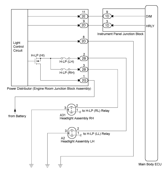
WIRING DIAGRAM
INSPECTION PROCEDURE
PROCEDURE
-
CHECK HEADLIGHT
-
Check the operation of LO-beam headlights.
OK LO-beam headlights operate normally.
NG 
GO TO PROBLEM SYMPTOMS TABLE Click here
OK 
-
-
PERFORM ACTIVE TEST USING INTELLIGENT TESTER
-
Connect the intelligent tester to the DLC3.
-
Turn the ignition switch on (IG).
-
Turn the intelligent tester on.
-
Select the following menu items: Body Electrical / Main Body / Active Test.
-
Check that the relay operates.
Main Body: Tester Display Test Part Control Range Diagnostic Note Head Light (HI) HI-beam headlight relay ON / OFF - OK Relay operates. (HI-beam headlights illuminate.)
NG 
INSPECT ENGINE ROOM JUNCTION BLOCK ASSEMBLY Click here
OK 
PROCEED TO NEXT CIRCUIT INSPECTION SHOWN IN PROBLEM SYMPTOMS TABLE Click here
-
-
INSPECT ENGINE ROOM JUNCTION BLOCK ASSEMBLY
-
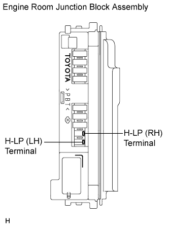
Remove the H-LP (RH) fuse and H-LP (LH) fuse from the engine room junction block assembly.
-
Measure the voltage between the loading slot of each fuse and body ground.
Standard voltage Tester Connection Condition Specified Condition H-LP (RH) terminal - Body ground Light control switch in HEAD and dimmer switch in HIGH 11 to 14 V H-LP (LH) terminal - Body ground Light control switch in HEAD and dimmer switch in HIGH 11 to 14 V
NG
REPAIR OR REPLACE HARNESS OR CONNECTOR (FUSE - BODY GROUND)
OK
-
-
INSPECT ENGINE ROOM JUNCTION BLOCK ASSEMBLY
-
Remove the engine room junction block assembly from the engine room relay block.
-
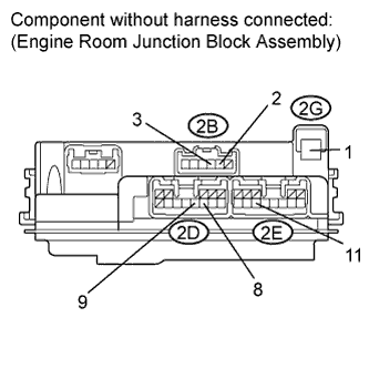
Connect the positive (+) lead from the battery to terminal 2G-1.
-
Connect the negative (-) lead from the battery to terminal 2D-8, 2D-9 and 2E-11.
-
Measure the voltage according to the value(s) in the table below.
Standard voltage Tester Connection Condition Specified Condition 2B-2 - Battery negative Always 11 to 14 V 2B-3 - Battery negative Always 11 to 14 V
NG
REPLACE ENGINE ROOM JUNCTION BLOCK ASSEMBLY
OK
-
-
CHECK HARNESS AND CONNECTOR (ENGINE ROOM JUNCTION BLOCK ASSEMBLY - MAIN BODY ECU)
-
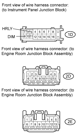
Disconnect the 2D and 2E engine room junction block assembly connectors.
-
Disconnect the 1D instrument panel junction block connector.
-
Measure the resistance according to the value(s) in the table below.
Standard resistance Tester Connection Condition Specified Condition 2E-11 - 1D-9 Always Below 1 Ω 2D-9 - 1D-3 Always Below 1 Ω 2E-11 - Body ground Always 10 kΩ or higher 2D-9 - Body ground Always 10 kΩ or higher
NG
REPAIR OR REPLACE HARNESS OR CONNECTOR
OK
REPLACE MAIN BODY ECU (INSTRUMENT PANEL JUNCTION BLOCK)
-