LIGHTING SYSTEM Headlight Relay Circuit
DESCRIPTION
-
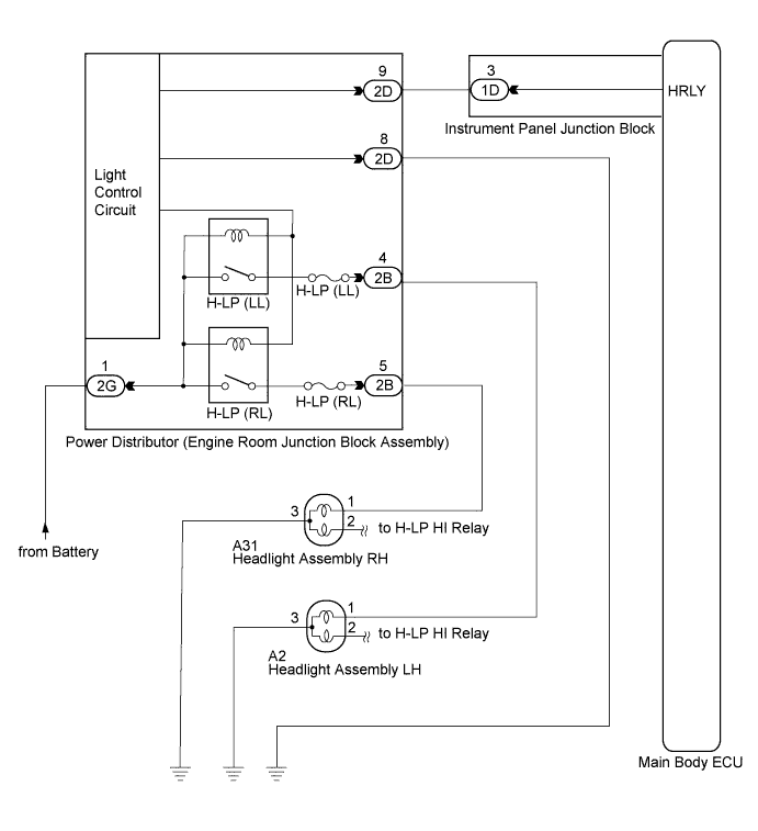
The main body receives the light control switch HEAD signal to control the headlight relays. The headlight relays are installed in the power distributor (engine room junction block assembly).
-
When the light control switch is in AUTO position, the main body ECU receives the ambient light level signal from the automatic light control sensor to control the headlight relays.
WIRING DIAGRAM
INSPECTION PROCEDURE
PROCEDURE
-
PERFORM ACTIVE TEST USING INTELLIGENT TESTER
-
Connect the intelligent tester to the DLC3.
-
Turn the ignition switch on (IG).
-
Turn the intelligent tester on.
-
Select the following menu items: Body Electrical / Main Body / Active Test.
-
Check that the relays operate.
Main Body: Tester Display Test Part Control Range Diagnostic Note Headlight Relay Headlight Relay ON/OFF - OK Headlight relays operate. (LO-beam headlights illuminate.)
NG 
INSPECT ENGINE ROOM JUNCTION BLOCK ASSEMBLY Click here
OK 
PROCEED TO NEXT CIRCUIT INSPECTION SHOWN IN PROBLEM SYMPTOMS TABLE Click here
-
-
INSPECT ENGINE ROOM JUNCTION BLOCK ASSEMBLY
-
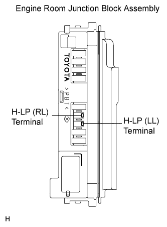
Remove the H-LP (LL) fuse and H-LP (RL) fuse from the engine room junction block assembly.
-
Measure the voltage between the loading slot of each fuse and body ground.
Standard voltage Tester Connection Switch Condition Specified Condition H-LP (LL) fuse terminal - Body ground Light control switch OFF → HEAD Below 1 V → 11 to 14 V H-LP (RL) fuse terminal - Body ground Light control switch OFF → HEAD Below 1 V → 11 to 14 V
NG
INSPECT ENGINE ROOM JUNCTION BLOCK ASSEMBLY Click here
OK
REPAIR OR REPLACE HARNESS OR CONNECTOR (FUSE - BODY GROUND)
-
-
INSPECT ENGINE ROOM JUNCTION BLOCK ASSEMBLY
-
Remove the engine room junction block assembly from the engine room relay block.
-
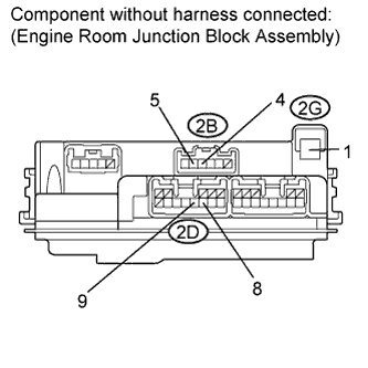
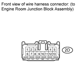
Connect the positive (+) lead from the battery to terminal 2G-1
-
Connect the negative (-) lead from the battery to terminal 2D-8 and 2D-9.
-
Measure the voltage according to the value(s) in the table below.
Standard voltage Tester Connection Condition Specified Condition 2B-4 - Battery negative Always 11 to 14 V 2B-5 - Battery negative Always 11 to 14 V
NG 
REPLACE ENGINE ROOM JUNCTION BLOCK ASSEMBLY
OK 
-
-
CHECK HARNESS AND CONNECTOR (BATTERY - ENGINE ROOM JUNCTION BLOCK ASSEMBLY)
-
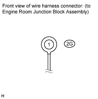
Disconnect the 2G engine room junction block assembly connector.
-
Measure the voltage according to the value(s) in the table below.
Standard voltage Tester Connector Condition Specified Condition 2G-1 - Body ground Always 11 to 14 V
NG
REPAIR OR REPLACE HARNESS OR CONNECTOR
OK
-
-
CHECK HARNESS AND CONNECTOR (ENGINE ROOM JUNCTION BLOCK ASSEMBLY - MAIN BODY ECU)
-
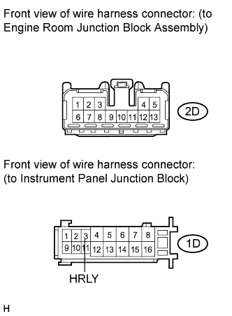
Disconnect the 2D engine room junction block assembly connector.
-
Disconnect the 1D instrument panel junction block connector.
-
Measure the resistance according to the value(s) in the table below.
Standard resistance Tester Connection Condition Specified Condition 2D-9 - 1D-3 Always Below 1 Ω 2D-9 - Body ground Always 10 kΩ or higher
NG
REPAIR OR REPLACE HARNESS OR CONNECTOR
OK
-
-
CHECK HARNESS AND CONNECTOR (ENGINE ROOM JUNCTION BLOCK ASSEMBLY - BODY GROUND)
-
Disconnect the 2D engine room junction block assembly connector.
-
Measure the resistance according to the value(s) in the table below.
Standard resistance Tester Connection Condition Specified Condition 2D-8 - Body ground Always Below 1 Ω
NG
REPAIR OR REPLACE HARNESS OR CONNECTOR
OK
REPLACE MAIN BODY ECU (INSTRUMENT PANEL JUNCTION BLOCK)
-