LIGHTING SYSTEM IG Signal Circuit
DESCRIPTION
-
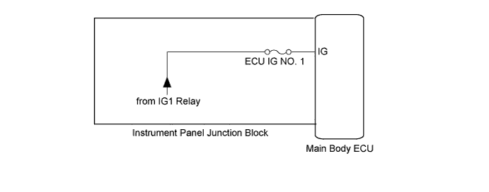
The main body ECU receives IG signal to control the following systems:
-
Automatic light control system
-
Light auto turn-off system
-
Illuminated entry system
WIRING DIAGRAM
INSPECTION PROCEDURE
PROCEDURE
-
READ VALUE USING INTELLIGENT TESTER
-
Connect the intelligent tester to the DLC3.
-
Turn the ignition switch on (IG).
-
Turn the intelligent tester on.
-
Select the following menu items: Body Electrical / Main Body / Data List.
-
Read the display on the intelligent tester.
Main Body: Tester Display Measurement Item/Range Normal Condition Diagnostic Note IG SW Ignition switch or engine switch IG signal / ON or OFF ON: Ignition switch on (IG)
OFF: Ignition switch off
- OK Normal conditions listed above are displayed.
NG 
INSPECT FUSE (ECU-IG NO. 1) Click here
OK 
PROCEED TO NEXT CIRCUIT INSPECTION SHOWN IN PROBLEM SYMPTOMS TABLE Click here
-
-
INSPECT FUSE (ECU-IG NO. 1)
-
Remove the ECU-IG No. 1 fuse from the instrument panel junction block.
-
Measure the resistance according to the value(s) in the table below.
Standard resistance Tester Connection Condition Specified Condition ECU-IG No. 1 fuse Always Below 1 Ω
NG 
REPLACE FUSE
OK 
-
-
CHECK HARNESS AND CONNECTOR (IG POWER SOURCE CIRCUIT)
-
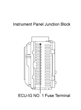
Measure the voltage between the loading slot of the fuse and body ground.
Standard voltage Tester Connection Switch Condition Specified Condition ECU-IG No. 1 fuse terminal - Body ground Ignition switch off Below 1 V Ignition switch on (IG) 11 to 14 V
NG
REPAIR OR REPLACE HARNESS OR CONNECTOR
OK
REPLACE MAIN BODY ECU (INSTRUMENT PANEL JUNCTION BLOCK)
-