Click here
-
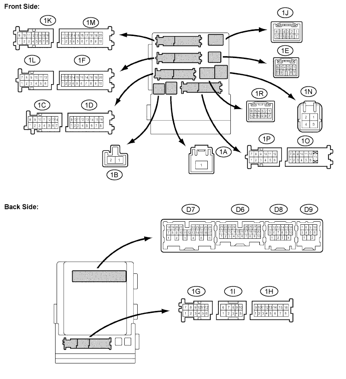
CHECK MAIN BODY ECU (INSTRUMENT PANEL JUNCTION BLOCK)
-
Disconnect the 1A, 1F and 1M junction block connectors.
-
Measure the voltage and resistance between the specified terminals of the wire harness side connectors and body ground.
Standard voltage Symbols Wiring Color Terminal Description Condition Specified Condition 1A-1 - Body ground B - Body ground Battery power supply Always 11 to 14 V Standard resistance Symbols Wiring Color Terminal Description Condition Specified Condition 1F-10 (GND1) - Body ground W-B - Body ground Ground Always Below 1 Ω 1M-9 (GND2) - Body ground W-B - Body ground Ground Always Below 1 Ω If the result is not as specified, there may be a malfunction on the wire harness side.
-
Reconnect the 1A, 1F and 1M junction block connectors.
-
Measure the resistance and voltage between the specified terminals of the junction block connectors and body ground.
Standard resistance Symbols Wiring Color Terminal Description Condition Specified Condition D6-18 (CLTE)*2 - Body ground
BR - Body ground Automatic light control ground Always Below 1 Ω Standard voltage Symbols Wiring Color Terminal Description Condition Specified Condition 1D-3 (HRLY) - Body ground P - Body ground Headlight relay drive output Light control switch in HEAD Below 1 V Light control switch not in HEAD 11 to 14 V 1D-9 (DIM) - Body ground L - Body ground High beam headlights drive output Dimmer switch in HIGH or HIGH FLASH Below 1 V Dimmer switch in LOW 11 to 14 V 1I-10 (ILE)*1 - Body ground
BR - Body ground Ignition key cylinder light drive output Ignition key cylinder light ON Below 1 V Ignition key cylinder light OFF 11 to 14 V 1N-2 (HU) - Body ground LG - Body ground Dimmer switch HIGH input Dimmer switch in HIGH or HIGH FLASH Below 1 V Dimmer switch in LOW 11 to 14 V 1O-7 (LCTY) - Body ground B - Body ground Rear door courtesy switch LH input Rear door LH open Below 1 V Rear door LH closed 11 to 14 V 1P-5 (LSWL) - Body ground G - Body ground Rear door lock position switch LH input Rear door LH locked 11 to 14 V Rear door LH unlocked Below 1 V 1R-5 (ILE) - Body ground SB - Body ground Interior lights drive output Interior lights ON Below 1 V Interior lights OFF 11 to 14 V D6-4 (MLRY)*3 - Body ground
R - Body ground Door mirror foot light drive output Door mirror foot light ON Below 1 V Door mirror foot light OFF 11 to 14 V D6-5 (LSWR) - Body ground B - Body ground Rear door lock position switch RH input Rear door RH locked 11 to 14 V Rear door RH unlocked Below 1 V D6-7 (RCTY) - Body ground GR - Body ground Rear door courtesy switch RH input Rear door RH open Below 1 V Rear door RH closed 11 to 14 V D6-9 (RFOG)*5 - Body ground
SB - Body ground Rear fog light switch input Rear fog light switch ON Below 1 V Rear fog light switch OFF 11 to 14 V D6-17 (HEAD) - Body ground P - Body ground Light control switch HEAD input Light control switch in HEAD Below 1 V Light control switch not in HEAD 11 to 14 V D6-19 (CLTS)*2 - Body ground
G - Body ground Automatic light control sensor signal input Ignition switch off Below 1 V Automatic light control system operates Pulse generation
(See waveform 1)
D6-20 (CLTB)*2 - Body ground
B - Body ground Automatic light control sensor power supply output Ignition switch off Below 1 V Ignition switch on (IG) and light control switch in AUTO 11 to 14 V D6-21 (PCTY) - Body ground SB (for LHD) - Body ground
G (for RHD) - Body ground
Front passenger side door courtesy switch input Front passenger side door open Below 1 V Front passenger side door closed 11 to 14 V D6-25 (BCTY) - Body ground L - Body ground Back door courtesy switch input Back door open Below 1 V Back door closed 11 to 14 V D6-27 (LSWP) - Body ground SB (for LHD) - Body ground
W (for RHD) - Body ground
Front passenger side door lock position switch input Front passenger side door locked 11 to 14 V Front passenger side door unlocked Below 1 V D6-28 (FFOG)*4 - Body ground
O - Body ground Front fog light switch input Front fog light switch ON Below 1 V Front fog light switch OFF 11 to 14 V D7-4 (FFGO)*4 - Body ground
O - Body ground Front fog light relay drive output Light control switch in HEAD and front fog light switch ON Below 1 V Front fog light switch OFF 11 to 14 V D7-9 (LSWD) - Body ground GR - Body ground Driver side door lock position switch input Driver side door locked 11 to 14 V Driver side door unlocked Below 1 V D7-13 (HF) - Body ground R - Body ground Dimmer switch HIGH FLASH signal input Dimmer switch in HIGH FLASH position Below 1 V Dimmer switch not in HIGH FLASH position 11 to 14 V D7-21 (A)*2 - Body ground
G - Body ground Light control switch AUTO signal input Light control switch in AUTO Below 1 V Light control switch not in AUTO 11 to 14 V D7-23 (TAIL) - Body ground SB - Body ground Light control switch TAIL signal input Light control switch in TAIL or HEAD Below 1 V Light control switch in neither TAIL nor HEAD 11 to 14 V D7-24 (DCTY) - Body ground G (for LHD) - Body ground
SB (for RHD) - Body ground
Driver side door courtesy switch input Driver side door open Below 1 V Driver side door closed 11 to 14 V D7-25 (SWIL)*2 - Body ground
R - Body ground Engine switch illumination drive output Engine switch illumination ON 11 to 14 V Engine switch illumination OFF Below 1 V D8-14 (RFGO)*5 - Body ground
R - Body ground Rear fog light relay drive output Light control switch in HEAD and rear fog light switch ON Below 1 V Rear fog light switch OFF 11 to 14 V If the result is not as specified, the main body ECU (Instrument panel junction block) may have a malfunction.
Tip:*1: w/o Smart Entry and Start System
*2: w/ Smart Entry and Start System
*3: w/ Door Mirror Foot Light
*4: w/ Front Fog Light
*5: w/ Rear Fog Light
-
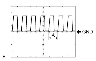
Waveform 1
Item Contents Tool setting 5 V/DIV., 5 ms./DIV. Tip:If the ambient light becomes brighter, width A becomes narrower.
-
-