LIGHTING SYSTEM Engine Switch Illumination Circuit
DESCRIPTION
The illuminated entry system controls the engine switch illumination.
WIRING DIAGRAM
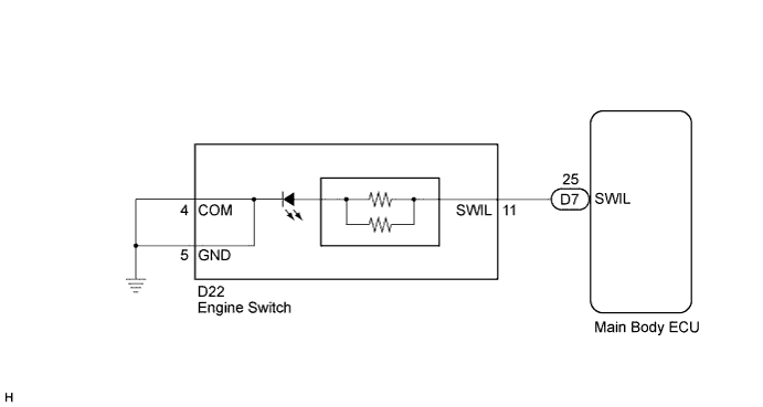
INSPECTION PROCEDURE
PROCEDURE
-
PERFORM ACTIVE TEST USING INTELLIGENT TESTER
-
Connect the intelligent tester to the DLC3.
-
Turn the ignition switch on (IG).
-
Turn the intelligent tester on.
-
Select the following menu items: Body Electrical / Main Body / Active Test.
-
Check the operation.
Main Body: Tester Display Test Part Control Range Diagnostic Note Indicator for Lighting Engine switch illumination ON / OFF - OK Engine switch illumination comes on.
NG 
INSPECT ENGINE SWITCH Click here
OK 
PROCEED TO NEXT CIRCUIT INSPECTION SHOWN IN PROBLEM SYMPTOMS TABLE Click here
-
-
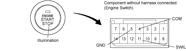
INSPECT ENGINE SWITCH
-
Remove the engine switch.
-
Apply battery voltage to the engine switch.
-
Check that the illumination comes on.
OK Measurement Condition Specified Condition Battery positive (+) → Terminal 11 (SWIL)
Battery negative (-) → Terminal 5 (GND) or 4 (COM)
Engine switch illumination comes on
NG 
REPLACE ENGINE SWITCH
OK 
-
-
CHECK HARNESS AND CONNECTOR (ENGINE SWITCH - MAIN BODY ECU AND BODY GROUND)
-
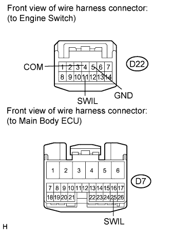
Disconnect the D7 main body ECU connector.
-
Disconnect the D22 engine switch connector.
-
Measure the resistance according to the value(s) in the table below.
Standard resistance Tester Connection Condition Specified Condition D22-11 (SWIL) - D7-25 (SWIL) Always Below 1 Ω D22-4 (COM) or D22-5 (GND) - Body ground Always Below 1 Ω D22-11 (SWIL) - Body ground Always 10 kΩ or higher
NG
REPAIR OR REPLACE HARNESS OR CONNECTOR
OK
REPLACE MAIN BODY ECU (INSTRUMENT PANEL JUNCTION BLOCK)
-