ENGINE IMMOBILISER SYSTEM (w/o Smart Entry and Start System) Diagnosis Circuit
DESCRIPTION
This circuit is used to read the DTCs that are output from the transponder key ECU assembly with the intelligent tester.
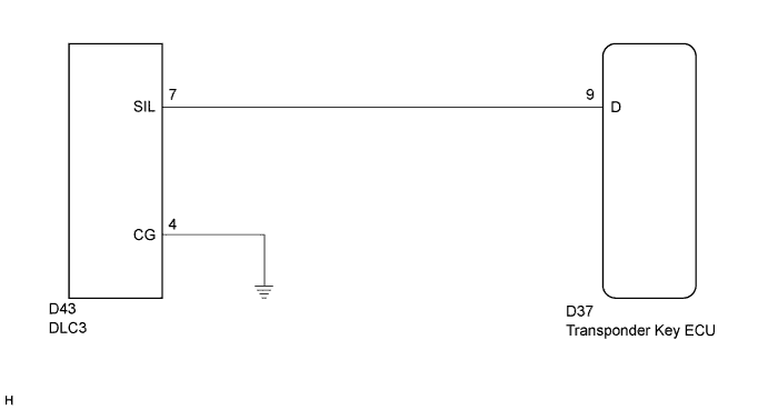
WIRING DIAGRAM
INSPECTION PROCEDURE
Note
If the transponder key ECU is replaced, register the key and ECU communication ID.
PROCEDURE
-
CHECK HARNESS AND CONNECTOR (TRANSPONDER KEY ECU - DLC3)
-
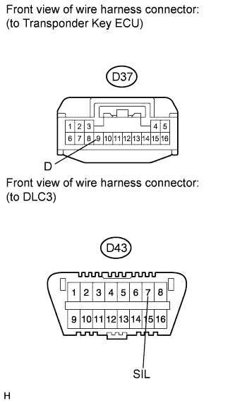
Disconnect the transponder key ECU connector.
-
Measure the resistance according to the value(s) in the table below.
Standard resistance Tester Connection Condition Specified Condition D37-9 (D) - D43-7 (SIL) Always Below 1 Ω D37-9 (D) - Body ground Always 10 kΩ or higher
NG 
REPAIR OR REPLACE HARNESS OR CONNECTOR
OK 
-
-
CHECK HARNESS AND CONNECTOR (DLC3 - BODY GROUND)
-
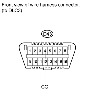
Measure the resistance according to the value(s) in the table below.
Standard resistance Tester Connection Condition Specified Condition D43-4 (CG) - Body ground Always Below 1 Ω
NG
REPAIR OR REPLACE HARNESS OR CONNECTOR
OK 
REPLACE TRANSPONDER KEY ECU ASSEMBLY
-