Click here
| DTC Code | DTC Name |
|---|---|
| ECU Power Source Circuit |
Click here
INSPECTION PROCEDURE
Note:
If the transponder key ECU is replaced, register the key and ECU communication ID.
Click here
PROCEDURE
- Click here
CHECK HARNESS AND CONNECTOR (TRANSPONDER KEY ECU - BATTERY)
-
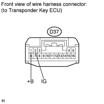
Disconnect the transponder key ECU connector.
-
Measure the voltage according to the value(s) in the table below.
Standard voltage Tester Connection Condition Specified Condition D37-1 (+B) - Body ground Always 11 to 14 V D37-2 (IG) - Body ground Ignition switch OFF Below 1 V D37-2 (IG) - Body ground Ignition switch ON 11 to 14 V
- OKClick here
- NGClick here
-
- Click here
CHECK HARNESS AND CONNECTOR (TRANSPONDER KEY ECU - BODY GROUND)
-

Measure the resistance according to the value(s) in the table below.
Standard resistance Tester Connection Condition Specified Condition D37-16 (GND) - Body ground Always Below 1 Ω
- OKClick here
- NGClick here
-
- Click here
REPAIR OR REPLACE HARNESS OR CONNECTOR, OR REPLACE FUSE
- Click here
REPAIR OR REPLACE HARNESS OR CONNECTOR
- Click here
REPLACE TRANSPONDER KEY ECU ASSEMBLY