ENGINE IMMOBILISER SYSTEM (w/o Smart Entry and Start System) Door Courtesy Switch Circuit
DESCRIPTION
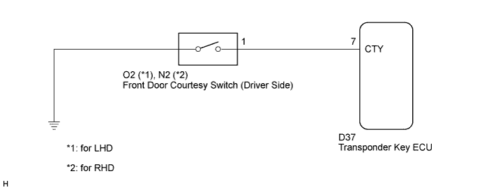
When an additional transponder key is registered, the transponder key ECU assembly detects the front door courtesy light switch open/closed condition, and enters the key registration mode.
WIRING DIAGRAM
INSPECTION PROCEDURE
Note
If the transponder key ECU is replaced, register the key and ECU communication ID.
PROCEDURE
-
CHECK HARNESS AND CONNECTOR (FRONT DOOR COURTESY LIGHT SWITCH CIRCUIT)
-
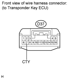
Disconnect the transponder key ECU connector.
-
Measure the resistance according to the value(s) in the table below.
Standard resistance Tester Connection Condition Specified Condition D37-7 (CTY) - Body ground Courtesy switch pushed
(Door closed)
10 kΩ or higher D37-7 (CTY) - Body ground Courtesy switch free
(Door open)
Below 1 Ω
NG 
INSPECT FRONT DOOR COURTESY LIGHT SWITCH ASSEMBLY Click here
OK 
REPLACE TRANSPONDER KEY ECU ASSEMBLY
-
-
INSPECT FRONT DOOR COURTESY LIGHT SWITCH ASSEMBLY
-
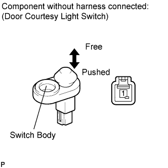
Remove the driver side front door courtesy light switch Click here.
-
Measure the resistance according to the value(s) in the table below.
Standard resistance Tester Connection Condition Specified Condition 1 - Switch body Courtesy switch pushed
(Door closed)
10 kΩ or higher 1 - Switch body Courtesy switch free
(Door open)
Below 1 Ω
NG 
REPLACE FRONT DOOR COURTESY LIGHT SWITCH ASSEMBLY Click here
OK
REPAIR OR REPLACE HARNESS OR CONNECTOR (TRANSPONDER KEY ECU - FRONT DOOR COURTESY LIGHT SWITCH)
-