ENGINE IMMOBILISER SYSTEM (w/o Smart Entry and Start System), Diagnostic DTC:B2784
| DTC Code | DTC Name |
|---|---|
| B2784 | Antenna Coil Open / Short |
DESCRIPTION
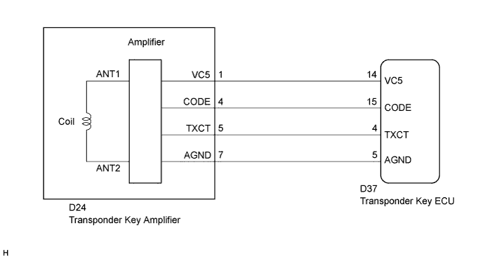
The transponder key coil is built into the transponder key amplifier and receives a key code signal from the transponder chip in the key. This signal is amplified by the amplifier, then it is output to the transponder key ECU assembly.
| DTC No. | DTC Detection Condition | Trouble Area |
|---|---|---|
| B2784 | Antenna coil is open/shorted |
|
WIRING DIAGRAM
INSPECTION PROCEDURE
Note
If the transponder key ECU is replaced, register the key and ECU communication ID.
PROCEDURE
-
READ VALUE ON INTELLIGENT TESTER (TRANSPONDER KEY AMPLIFIER)
-
Connect the intelligent tester to the DLC3.
-
Turn the ignition switch to the ON position.
-
Turn the tester on.
-
Select Antenna Coil Status in the Data List and read the tester display.
Immobiliser (Transponder Key ECU): Tester Display Measurement Item/Range Normal Condition Diagnostic Note Antenna Coil Status Transponder key amplifier coil condition/NORMAL or FAIL NORMAL: Antenna coil is normal
FAIL: Antenna coil is malfunctioning
- OK NORMAL (Antenna coil is normal) appears on the screen.
NG 
CHECK HARNESS AND CONNECTOR (TRANSPONDER KEY ECU - TRANSPONDER KEY AMPLIFIER) Click here
OK 
REPLACE TRANSPONDER KEY ECU ASSEMBLY
-
-
CHECK HARNESS AND CONNECTOR (TRANSPONDER KEY ECU - TRANSPONDER KEY AMPLIFIER)
-
Disconnect the transponder key ECU and transponder key amplifier connectors.
-
Measure the resistance according to the value(s) in the table below.
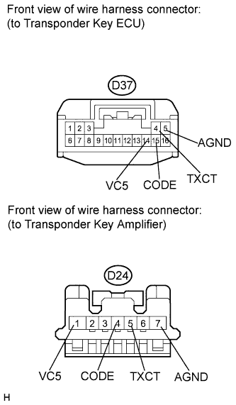
Standard resistance Tester Connection Condition Specified Condition D37-4 (TXCT) - D24-5 (TXCT) Always Below 1 Ω D37-5 (AGND) - D24-7 (AGND) Always Below 1 Ω D37-14 (VC5) - D24-1 (VC5) Always Below 1 Ω D37-15 (CODE) - D24-4 (CODE) Always Below 1 Ω D37-4 (TXCT) - Body ground Always 10 kΩ or higher D37-5 (AGND) - Body ground Always 10 kΩ or higher D37-14 (VC5) - Body ground Always 10 kΩ or higher D37-15 (CODE) - Body ground Always 10 kΩ or higher
NG 
REPAIR OR REPLACE HARNESS OR CONNECTOR
OK 
-
-
INSPECT TRANSPONDER KEY ECU ASSEMBLY (TRANSPONDER KEY AMPLIFIER POWER SOURCE)
-
Reconnect the transponder key ECU and transponder key amplifier connectors.
-
Measure the voltage according to the value(s) in the table below.
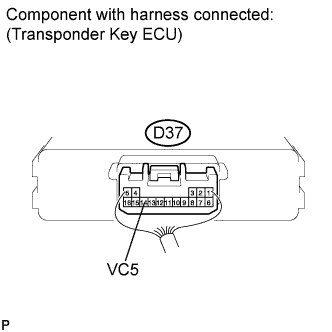
Standard voltage Tester Connection Condition Specified Condition D37-14 (VC5) - Body ground No key is in ignition key cylinder Below 1 V D37-14 (VC5) - Body ground Key is in ignition key cylinder 4.6 to 5.4 V
NG
REPLACE TRANSPONDER KEY ECU ASSEMBLY
OK
-
-
INSPECT TRANSPONDER KEY ECU ASSEMBLY (TRANSPONDER KEY AMPLIFIER GROUND)
-
Measure the resistance according to the value(s) in the table below.
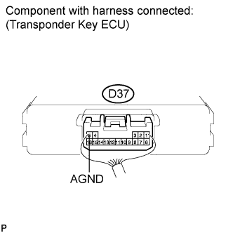
Standard resistance Tester Connection Condition Specified Condition D37-5 (AGND) - Body ground Always Below 1 Ω
NG
REPLACE TRANSPONDER KEY ECU ASSEMBLY
OK
REPLACE TRANSPONDER KEY AMPLIFIER Click here
-