| DTC Code | DTC Name |
|---|---|
| Certification ECU Power Source Circuit |
DESCRIPTION
This is the power source circuit of the certification ECU (smart key ECU assembly).
The certification ECU (smart key ECU assembly) controls the following:
-
Electrical key verification confirmation
-
Indoor, outside and door oscillator control
-
Entry door LOCK/UNLOCK request to the main body ECU (instrument panel junction block)
-
Steering LOCK/UNLOCK request
-
Immobiliser SET/UNSET request to the ID code box (immobiliser code ECU)
INSPECTION PROCEDURE
If the certification ECU (smart key ECU assembly) is replaced, register the key and ECU communication ID.
PROCEDURE
- Click here
CHECK HARNESS AND CONNECTOR (CERTIFICATION ECU - BATTERY)
-
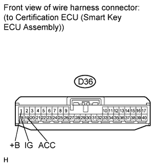
Disconnect the certification ECU (smart key ECU assembly) connector.
-
Measure the voltage according to the value(s) in the table below.
Standard voltage Tester Connection Condition Specified Condition D36-1 (+B) - Body ground Always 11 to 14 V D36-18 (IG) - Body ground Engine switch off Below 1 V D36-18 (IG) - Body ground Engine switch on (IG) 11 to 14 V D36-19 (ACC) - Body ground Engine switch off Below 1 V D36-19 (ACC) - Body ground Engine switch on (ACC) 11 to 14 V
- OKClick here
- NGClick here
-
- Click here
CHECK HARNESS AND CONNECTOR (CERTIFICATION ECU - BODY GROUND)
-
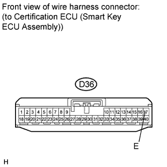
Measure the resistance according to the value(s) in the table below.
Standard resistance Tester Connection Condition Specified Condition D36-17 (E) - Body ground Always Below 1 Ω
- OKClick here
- NGClick here
-
- Click here
REPLACE CERTIFICATION ECU (SMART KEY ECU ASSEMBLY)
- Click here
REPAIR OR REPLACE HARNESS OR CONNECTOR, OR REPLACE FUSE
- Click here
REPAIR OR REPLACE HARNESS OR CONNECTOR