ENGINE IMMOBILISER SYSTEM (w/ Smart Entry and Start System) ID Code Box Power Source Circuit
DESCRIPTION
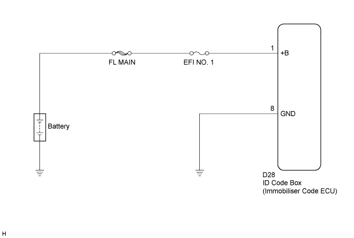
This circuit provides power to operate the ID code box (immobiliser code ECU).
WIRING DIAGRAM
INSPECTION PROCEDURE
Note
If the ID code box (immobiliser code ECU) is replaced, register the ECU code and ECU communication ID.
PROCEDURE
-
CHECK HARNESS AND CONNECTOR (ID CODE BOX - BATTERY)
-
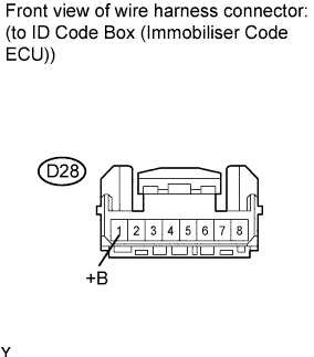
Disconnect the ID code box (immobiliser code ECU) connector.
-
Measure the voltage according to the value(s) in the table below.
Standard voltage Tester Connection Condition Specified Condition D28-1 (+B) - Body ground Always 11 to 14 V
NG 
REPAIR OR REPLACE HARNESS OR CONNECTOR, OR REPLACE FUSE
OK 
-
-
CHECK HARNESS AND CONNECTOR (ID CODE BOX - BODY GROUND)
-
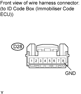
Measure the resistance according to the value(s) in the table below.
Standard resistance Tester Connection Condition Specified Condition D28-8 (GND) - Body ground Always Below 1 Ω
NG
REPAIR OR REPLACE HARNESS OR CONNECTOR
OK 
REPLACE ID CODE BOX (IMMOBILISER CODE ECU)
-