ENGINE IMMOBILISER SYSTEM (w/ Smart Entry and Start System), Diagnostic DTC:B278A
| DTC Code | DTC Name |
|---|---|
| B278A | Short to GND in Immobiliser System Power Source Circuit |
DESCRIPTION
This DTC is output when the engine switch power source supply line is open or shorted.
| DTC No. | DTC Detection Condition | Trouble Area |
|---|---|---|
| B278A | Engine switch power source supply line is open or shorted |
|
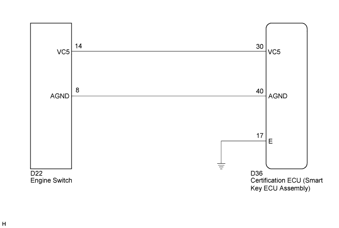
WIRING DIAGRAM
INSPECTION PROCEDURE
Note
If the certification ECU (smart key ECU assembly) is replaced, register the key and ECU communication ID.
PROCEDURE
-
CHECK DTC OUTPUT
-
Delete the DTCs Click here.
-
Recheck for DTCs.
OK B278A output does not recur.
NG 
CHECK HARNESS AND CONNECTOR (CERTIFICATION ECU - ENGINE SWITCH) Click here
OK 
USE SIMULATION METHOD TO CHECK Click here
-
-
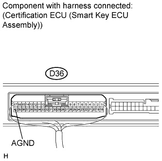
CHECK HARNESS AND CONNECTOR (CERTIFICATION ECU - ENGINE SWITCH)
-
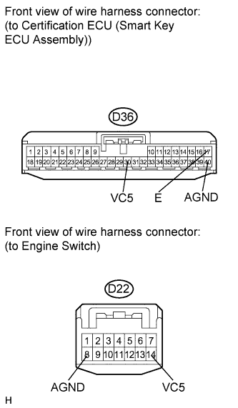
Disconnect the certification ECU (smart key ECU assembly) and engine switch connectors.
-
Measure the resistance according to the value(s) in the table below.
Standard resistance Tester Connection Condition Specified Condition D36-30 (VC5) - D22-14 (VC5) Always Below 1 Ω D36-40 (AGND) - D22-8 (AGND) Always Below 1 Ω D36-17 (E) - Body ground Always Below 1 Ω D36-30 (VC5) - Body ground Always 10 kΩ or higher D36-40 (AGND) - Body ground Always 10 kΩ or higher
NG 
REPAIR OR REPLACE HARNESS OR CONNECTOR
OK 
-
-
CHECK HARNESS AND CONNECTOR (ENGINE SWITCH POWER SOURCE)
-
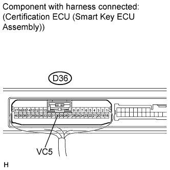
Reconnect the certification ECU (smart key ECU assembly) and engine switch connectors.
-
Measure the voltage according to the value(s) in the table below.
Standard voltage Tester Connection Condition Specified Condition D36-30 (VC5) - Body ground Engine switch off, brake pedal not depressed, 30 seconds or more elapsed after driver door opened and then closed Below 1 V -
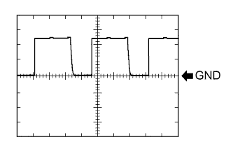
Using an oscilloscope, check the waveform.
Measurement condition Tester Connection Condition Tool Setting Specified Condition D36-30 (VC5) - Body ground Engine switch off, key not in cabin, within 30 seconds after engine switch pressed 2 V/DIV., 200 ms./DIV. Pulse generation OK The waveform is similar to that shown in the illustration.
NG
REPLACE CERTIFICATION ECU (SMART KEY ECU ASSEMBLY)
OK
-
-
CHECK HARNESS AND CONNECTOR (ENGINE SWITCH BODY GROUND)
-
Measure the resistance according to the value(s) in the table below.
Standard resistance Tester Connection Condition Specified Condition D36-40 (AGND) - Body ground Always Below 1 Ω
NG
REPLACE CERTIFICATION ECU (SMART KEY ECU ASSEMBLY)
OK
REPLACE ENGINE SWITCH Click here
-