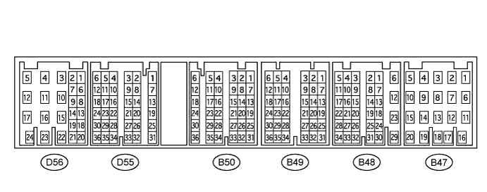
ENGINE IMMOBILISER SYSTEM (w/o Smart Entry and Start System) TERMINALS OF ECU
-
CHECK TRANSPONDER KEY AMPLIFIER
-
Disconnect the D24 transponder key amplifier connector and measure the resistance according to the value(s) in the table below.

Tester Connection Wiring Color Terminal Description Condition Specified Condition D24-7 (AGND) - Body ground G - Body ground Ground Always Below 1 Ω If the result is not as specified, there may be a malfunction on the wire harness side.
-
Reconnect the D24 transponder key amplifier connector and measure the voltage according to the value(s) in the table below.
Tester Connection Wiring Color Terminal Description Condition Specified Condition D24-1 (VC5) - D24-7 (AGND) P - G Power source No key is in ignition key cylinder Below 1 V D24-1 (VC5) - D24-7 (AGND) P - G Power source Key is in ignition key cylinder 4.6 to 5.4 V D24-4 (CODE) - D24-7 (AGND) R - G Demodulated signal of key code data No key is in ignition key cylinder Below 1 V D24-4 (CODE) - D24-7 (AGND) R - G Demodulated signal of key code data Key is in ignition key cylinder Waveform 1 D24-5 (TXCT) - D24-7 (AGND) SB - G Key code output signal No key is in ignition key cylinder Below 1 V D24-5 (TXCT) - D24-7 (AGND) SB - G Key code output signal Key is in ignition key cylinder Waveform 2 If the result is not as specified, the transponder key amplifier may have a malfunction.
-
Inspect using an oscilloscope.
-
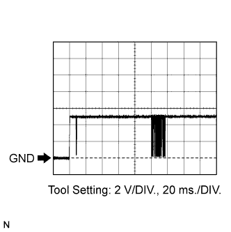
Waveform 1 (Reference)
Item Content Tester Connection D24-4 (CODE) - D24-7 (AGND) Tool Setting 2 V/DIV., 20 ms./DIV. Condition Key is in ignition key cylinder -
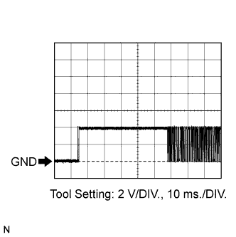
Waveform 2 (Reference)
Item Content Tester Connection D24-5 (TXCT) - D24-7 (AGND) Tool Setting 2 V/DIV., 10 ms./DIV. Condition Key is in ignition key cylinder
-
-
-
CHECK TRANSPONDER KEY ECU ASSEMBLY
-
Disconnect the D37 transponder key ECU connector and measure the resistance and voltage according to the value(s) in the table below.

Tester Connection Wiring Color Terminal Description Condition Specified Condition D37-1 (+B) - D37-16 (GND) GR - V Battery Always 11 to 14 V D37-2 (IG) - D37-16 (GND) P - V Ignition switch signal Ignition switch OFF Below 1 V D37-2 (IG) - D37-16 (GND) P - V Ignition switch signal Ignition switch ON 11 to 14 V D37-3 (KSW) - D37-16 (GND) BE - V Unlock warning switch signal No key is in ignition key cylinder 10 kΩ or higher D37-3 (KSW) - D37-16 (GND) BE - V Unlock warning switch signal Key is in ignition key cylinder Below 1 Ω D37-16 (GND) - Body ground V - Body ground Ground Always Below 1 Ω If the result is not as specified, there may be a malfunction on the wire harness side.
-
Reconnect the D37 transponder key ECU connector and measure the resistance and voltage according to the value(s) in the table below.
Tester Connection Wiring Color Terminal Description Condition Specified Condition D37-3 (KSW) - D37-16 (GND) BE - V Unlock warning switch signal No key is in ignition key cylinder 11 to 14 V D37-3 (KSW) - D37-16 (GND) BE - V Unlock warning switch signal Key is in ignition key cylinder Below 1 V D37-4 (TXCT) - D37-5 (AGND) SB - G Transponder key amplifier communication signal No key is in ignition key cylinder Below 1 V D37-4 (TXCT) - D37-5 (AGND) SB - G Transponder key amplifier communication signal Key is in ignition key cylinder Waveform 1 D37-5 (AGND) - Body ground G - Body ground Ground Always Below 1 Ω D37-7 (CTY) - D37-16 (GND) LG - V Door courtesy signal Switch pushed 11 to 14 V D37-7 (CTY) - D37-16 (GND) LG - V Door courtesy signal Switch free Below 1 V D37-8 (IND) - D37-16 (GND) Y - V Security indicator light signal Security indicator light is on 11 to 14 V D37-8 (IND) - D37-16 (GND) Y - V Security indicator light signal Security indicator light is off Below 1 V D37-9 (D) - D37-16 (GND) B - V Diagnostic tester communication Without communication Below 1 V D37-9 (D) - D37-16 (GND) B - V Diagnostic tester communication During communication Pulse generation D37-12 (EFII) - D37-16 (GND) V - V ECM input signal Ignition switch OFF 11 to 14 V D37-12 (EFII) - D37-16 (GND) V - V ECM input signal Within 3 seconds after starter operates and initial combustion occurs, or within 3 seconds after ignition switch first turned to ON after battery disconnected and connected. Waveform 2 D37-13 (EFIO) - D37-16 (GND) L - V ECM output signal Ignition switch OFF Below 1 V D37-13 (EFIO) - D37-16 (GND) L - V ECM output signal Ignition switch ON Waveform 3 D37-14 (VC5) - D37-5 (AGND) P - G Power source No key is in ignition key cylinder Below 1 V D37-14 (VC5) - D37-5 (AGND) P - G Power source Key is in ignition key cylinder 4.6 to 5.4 V D37-15 (CODE) - D37-5 (AGND) R - G Transponder key amplifier communication signal No key is in ignition key cylinder Below 1 V D37-15 (CODE) - D37-5 (AGND) R - G Transponder key amplifier communication signal Key is in ignition key cylinder Waveform 4 If the result is not as specified, the transponder key ECU may have a malfunction.
-
Inspect using an oscilloscope.
-
Waveform 1 (Reference)
Item Content Tester Connection D37-4 (TXCT) - D37-5 (AGND) Tool Setting 2 V/DIV., 10 ms./DIV. Condition Key is in ignition key cylinder -
Waveform 2 (Reference)
Item Content Tester Connection D37-12 (EFII) - D37-16 (GND) Tool Setting 5 V/DIV., 500 ms./DIV. Condition Within 3 seconds after starter operates and initial combustion occurs, or within 3 seconds after ignition switch first turned to ON after battery disconnected and connected. -
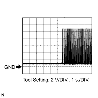
Waveform 3 (Reference)
Item Content Tester Connection D37-13 (EFIO) - D37-16 (GND) Tool Setting 2 V/DIV., 1 s./DIV. Condition Ignition switch ON -
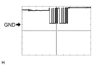
Waveform 4 (Reference)
Item Content Tester Connection D37-15 (CODE) - D37-5 (AGND) Tool Setting 2 V/DIV., 20 ms./DIV. Condition Key is in ignition key cylinder
-
-
-
CHECK ECM
-
Disconnect the B48 ECM connector and measure the resistance according to the value(s) in the table below.
Tester Connection Wiring Color Terminal Description Condition Specified Condition B48-12 (E1) - Body ground W-B - Body ground Ground Always Below 1 Ω If the result is not as specified, there may be a malfunction on the wire harness side.
-
Reconnect the B48 ECM connector. Measure the voltage according to the value(s) in the table below.
Tester Connection Wiring Color Terminal Description Condition Specified Condition D55-20 (IMO) - B48-12 (E1) V - W-B Transponder key ECU output signal Ignition switch off 11 to 14 V D55-20 (IMO) - B48-12 (E1) V - W-B Transponder key ECU output signal Within 3 seconds after starter operates and initial combustion occurs, or within 3 seconds after ignition switch first turned to ON after battery disconnected and connected. Waveform 1 D55-14 (IMI) - B48-12 (E1) L - W-B Transponder key ECU input signal Ignition switch off Below 1 V D55-14 (IMI) - B48-12 (E1) L - W-B Transponder key ECU input signal Ignition switch ON Waveform 2 If the result is not as specified, the ECM may have a malfunction.
-
Inspect using an oscilloscope.
-
Waveform 1 (Reference)
Item Content Tester Connection D55-20 (IMO) - B48-12 (E1) Tool Setting 5 V/DIV., 500 ms./DIV. Condition Within 3 seconds after starter operates and initial combustion occurs, or within 3 seconds after ignition switch first turned to ON after battery disconnected and connected. -
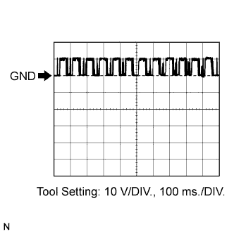
Waveform 2 (Reference)
Item Content Tester Connection D55-14 (IMI) - B48-12 (E1) Tool Setting 10 V/DIV., 100 ms./DIV. Condition Ignition switch ON
-
-