ENGINE IMMOBILISER SYSTEM (w/o Smart Entry and Start System), Diagnostic DTC:B2780
| DTC Code | DTC Name |
|---|---|
| B2780 | Push Switch / Key Unlock Warning Switch Malfunction |
DESCRIPTION
This DTC will be output if the transponder key ECU assembly does not detect that the unlock warning switch is on even when the ignition switch is in the ON position. Under normal conditions, the unlock warning switch is on when the ignition switch is in the ON position.
| DTC No. | DTC Detection Condition | Trouble Area |
|---|---|---|
| B2780 | "Unlock warning switch ON" is not detected when ignition switch is ON |
|
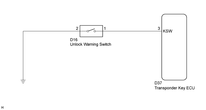
WIRING DIAGRAM
INSPECTION PROCEDURE
Note
If the transponder key ECU is replaced, register the key and ECU communication ID.
PROCEDURE
-
READ VALUE ON INTELLIGENT TESTER (UNLOCK WARNING SWITCH)
-
Connect the intelligent tester to the DLC3.
-
Turn the ignition switch to the ON position.
-
Turn the tester on.
-
Select Key SW in the Data List and read the tester display.
Immobiliser (Transponder Key ECU): Tester Display Measurement Item/Range Normal Condition Diagnostic Note Key SW Unlock warning switch signal/ON or OFF ON: Key is in ignition key cylinder
OFF: No key is in ignition key cylinder
- OK ON (Key is in ignition key cylinder) appears on the screen.
NG 
INSPECT UNLOCK WARNING SWITCH ASSEMBLY Click here
OK 
REPLACE TRANSPONDER KEY ECU ASSEMBLY
-
-
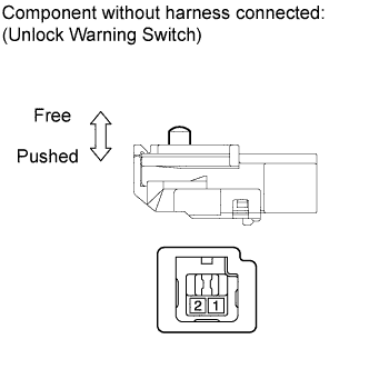
INSPECT UNLOCK WARNING SWITCH ASSEMBLY
-
Remove the unlock warning switch assembly Click here.
-
Measure the resistance according to the value(s) in the table below.
Standard resistance Tester Connection Switch Position Specified Condition 1 - 2 Switch pushed
(Key inserted)
Below 1 Ω 1 - 2 Switch free
(Key removed)
10 kΩ or higher
NG 
REPLACE UNLOCK WARNING SWITCH ASSEMBLY Click here
OK 
-
-
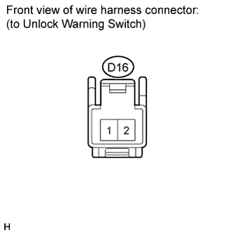
CHECK HARNESS AND CONNECTOR (UNLOCK WARNING SWITCH - BODY GROUND)
-
Measure the resistance according to the value(s) in the table below.
Standard resistance Tester Connection Condition Specified Condition D16-2 - Body ground Always Below 1 Ω
NG
REPAIR OR REPLACE HARNESS OR CONNECTOR
OK
-
-
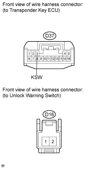
CHECK HARNESS AND CONNECTOR (TRANSPONDER KEY ECU - UNLOCK WARNING SWITCH)
-
Disconnect the transponder key ECU connector.
-
Measure the resistance according to the value(s) in the table below.
Standard resistance Tester Connection Condition Specified Condition D37-3 (KSW) - D16-1 Always Below 1 Ω D16-1 - Body ground Always 10 kΩ or higher
NG
REPAIR OR REPLACE HARNESS OR CONNECTOR
OK
REPLACE TRANSPONDER KEY ECU ASSEMBLY
-