THEFT DETERRENT SYSTEM (w/o Smart Entry and Start System) Security Horn Circuit
DESCRIPTION
When the theft deterrent system is switched from the armed state to the alarm sounding state, the main body ECU controls the security horn.
WIRING DIAGRAM
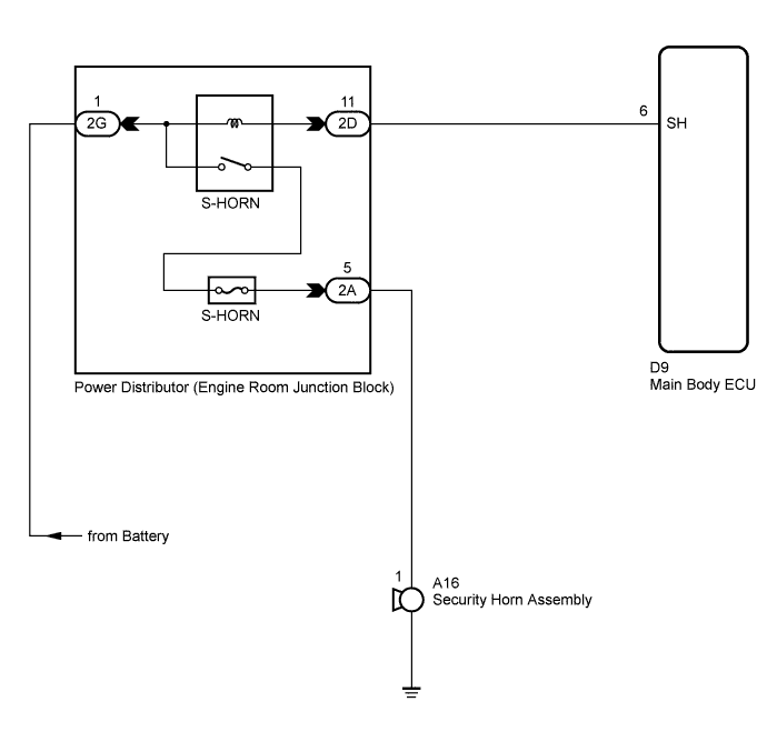
INSPECTION PROCEDURE
PROCEDURE
-
CHECK HARNESS AND CONNECTOR (MAIN BODY ECU - ENGINE ROOM JUNCTION BLOCK)
-
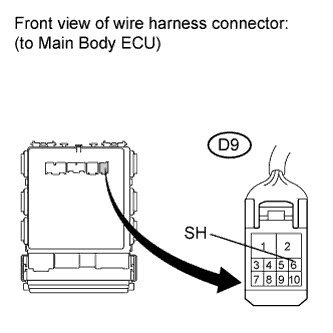
Disconnect the D9 ECU connector.
-
Connect a negative battery lead to terminal 6 (SH) of the D9 ECU connector.
-
Check operation of the security horn.
OK Measurement Condition Specified Condition Battery negative (-) → D9-6 (SH) Horn sounds
NG 
INSPECT SECURITY HORN ASSEMBLY Click here
OK 
PROCEED TO NEXT CIRCUIT INSPECTION SHOWN IN PROBLEM SYMPTOMS TABLE Click here
-
-
INSPECT SECURITY HORN ASSEMBLY
-
Remove the security horn assembly Click here.
-
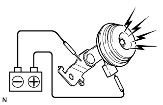
Connect a positive battery lead to terminal 1 of the security horn assembly, and a negative battery lead to the horn body.
-
Check operation of the horn.
OK Measurement Condition Specified Condition Battery positive (+) → Terminal 1 Horn sounds Battery negative (-) → Horn body
NG 
REPLACE SECURITY HORN ASSEMBLY Click here
OK 
-
-
CHECK HARNESS AND CONNECTOR (ENGINE ROOM JUNCTION BLOCK - SECURITY HORN ASSEMBLY)
-
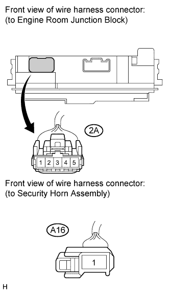
Disconnect the 2A engine room junction block connector and A16 security horn assembly connector.
-
Measure the resistance according to the value(s) in the table below.
Standard resistance Tester Connection Condition Specified Condition 2A-5 - A16-1 Always Below 1 Ω 2A-5 - Body ground Always 10 kΩ or higher
NG
REPAIR OR REPLACE HARNESS OR CONNECTOR
OK
-
-
CHECK HARNESS AND CONNECTOR (BATTERY - ENGINE ROOM JUNCTION BLOCK)
-
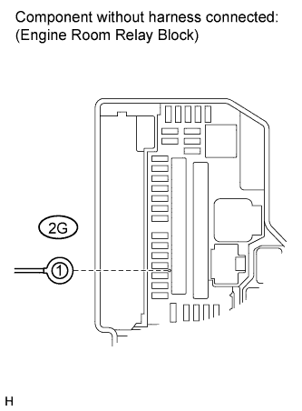
Disconnect the 2G engine room junction block assembly connector.
-
Measure the voltage on the junction block side according to the value(s) in the table below.
Standard voltage Tester Connection Condition Specified Condition 2G-1 - Body ground Always 11 to 14 V
NG
REPAIR OR REPLACE HARNESS OR CONNECTOR
OK
-
-
CHECK HARNESS AND CONNECTOR (ENGINE ROOM JUNCTION BLOCK - MAIN BODY ECU)
-
Disconnect the 2D engine room junction block connector.
-
Disconnect the D9 ECU connector.
-
Measure the resistance according to the value(s) in the table below.
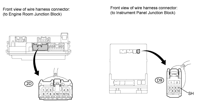
Standard resistance Tester Connection Condition Specified Condition 2D-11 - D9-6 (SH) Always Below 1 Ω D9-6 (SH) - Body ground Always 10 kΩ or higher
NG
REPAIR OR REPLACE HARNESS OR CONNECTOR
OK
REPLACE ENGINE ROOM JUNCTION BLOCK
-