Click here
| DTC Code | DTC Name |
|---|---|
| ECU Power Source Circuit |
Click here
INSPECTION PROCEDURE
Click here
PROCEDURE
- Click here
CHECK INSTRUMENT PANEL JUNCTION BLOCK (MAIN BODY ECU (POWER SOURCE))
-
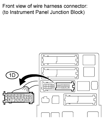
Disconnect the 1D junction block connector.
-
Measure the voltage according to the value(s) in the table below.
Standard voltage Tester Connection Specified Condition 1D-16 - Body ground 11 to 14 V
- OKClick here
- NGClick here
-
- Click here
CHECK HARNESS AND CONNECTOR (INSTRUMENT PANEL JUNCTION BLOCK - BODY GROUND)
-
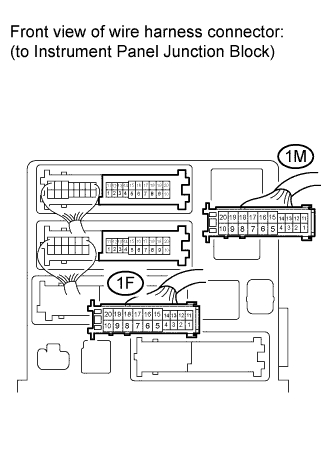
Disconnect the 1F and 1M junction block connectors.
-
Measure the resistance according to the value(s) in the table below.
Standard resistance Tester Connection Specified Condition 1F-10 - Body ground Below 1 Ω 1M-9 - Body ground Below 1 Ω
- OKClick here
- NGClick here
-
- Click here
PROCEED TO NEXT CIRCUIT INSPECTION SHOWN IN PROBLEM SYMPTOMS TABLEClick here
- Click here
REPAIR OR REPLACE HARNESS OR CONNECTOR