THEFT DETERRENT SYSTEM (w/ Smart Entry and Start System) Horn Circuit
DESCRIPTION
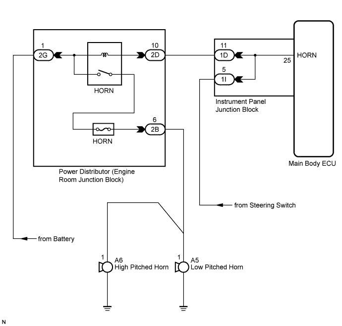
When the theft deterrent system is switched from the armed state to the alarm sounding state, the main body ECU transmits a signal to cause the horn to sound at 0.4 second intervals.
WIRING DIAGRAM
INSPECTION PROCEDURE
PROCEDURE
-
INSPECT HORNS
-
Press the horn switch and check if the horns sound.
Result Result Proceed to Horns sound A Horns do not sound B
B 
GO TO HORN SYSTEM Click here
A 
-
-
PERFORM ACTIVE TEST USING INTELLIGENT TESTER
-
Connect the intelligent tester to the DLC3.
-
Turn the engine switch on (IG).
-
Turn the intelligent tester main switch on.
-
Select the item below in the Active Test and then check that the horns operate.
Main Body: Tester Display Test Part Control Range Diagnostic Note Vehicle Horn Vehicle horns ON / OFF - OK The vehicle horns sound and stop correctly when operating them through the intelligent tester.
NG 
CHECK HARNESS AND CONNECTOR (INSTRUMENT PANEL JUNCTION BLOCK - ENGINE ROOM JUNCTION BLOCK) Click here
OK 
PROCEED TO NEXT CIRCUIT INSPECTION SHOWN IN PROBLEM SYMPTOMS TABLE Click here
-
-
CHECK HARNESS AND CONNECTOR (INSTRUMENT PANEL JUNCTION BLOCK - ENGINE ROOM JUNCTION BLOCK)
-
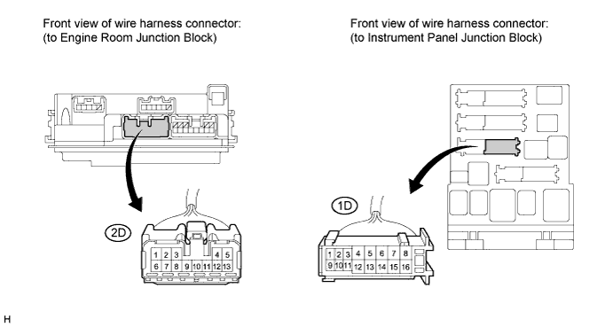
Disconnect the 1D instrument panel junction block connector and 2D engine room junction block connector.
-
Measure the resistance according to the value(s) in the table below.
Standard resistance Tester Connection Condition Specified Condition 1D-11 - 2D-10 Always Below 1 Ω 1D-11 - Body ground Always 10 kΩ or higher
NG
REPAIR OR REPLACE HARNESS OR CONNECTOR
OK
REPLACE MAIN BODY ECU (INSTRUMENT PANEL JUNCTION BLOCK)
-