Click here
-
CHECK MAIN BODY ECU (INSTRUMENT PANEL JUNCTION BLOCK)
-
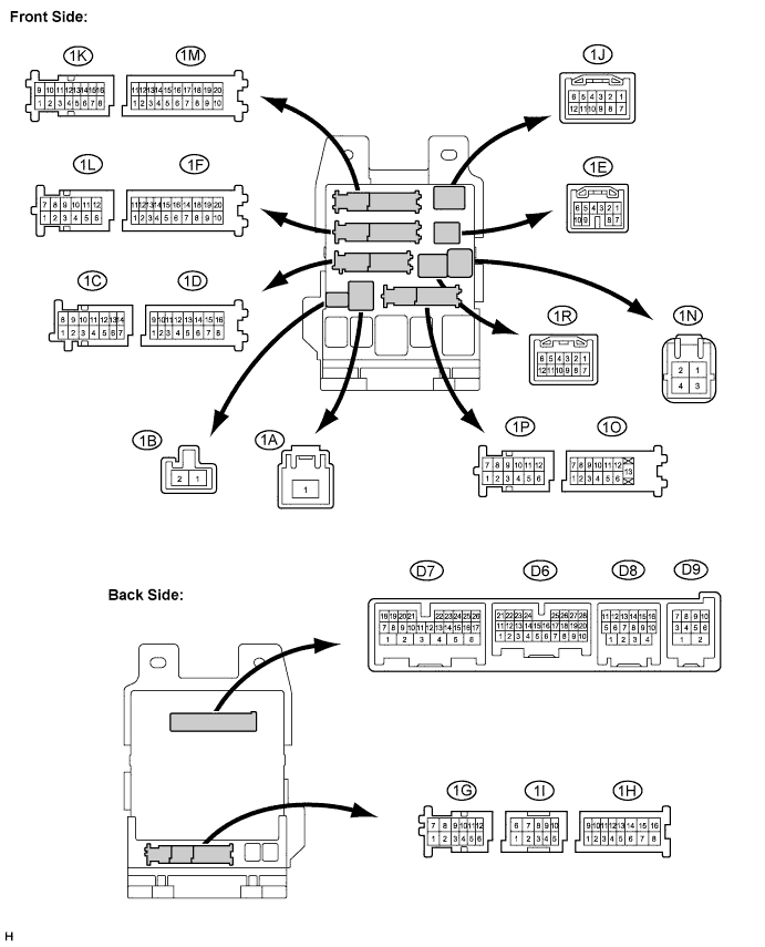
Disconnect the main body ECU (instrument panel junction block) connectors.
-
Measure the resistance and voltage between each terminal of the wire harness side connectors and body ground.
Tester Connection Wiring Color Terminal Description Condition Specified Condition D6-7 (RCTY) - Body ground GR - Body ground Rear courtesy light switch RH input Rear door RH CLOSED (OFF) → OPEN (ON) 10 kΩ or higher → Below 1 Ω D6-21 (PCTY) - Body ground SB*1 - Body ground
Passenger side courtesy light switch input Passenger side door CLOSED (OFF) → OPEN (ON) 10 kΩ or higher → Below 1 Ω G*2 - Body ground
D6-25 (BCTY) - Body ground L - Body ground Back door courtesy light switch input Back door CLOSED (OFF) → OPEN (ON) 10 kΩ or higher → Below 1 Ω D7-24 (DCTY) - Body ground G*1 - Body ground
Driver side door courtesy light switch input Driver side door CLOSED (OFF) → OPEN (ON) 10 kΩ or higher → Below 1 Ω SB*2 - Body ground
D9-8 (GHSW) - Body ground O - Body ground Glass hatch courtesy switch Glass hatch CLOSED (OFF) → OPEN (ON) 10 kΩ or higher → Below 1 Ω 1A-1 (ACC) - Body ground B - Body ground Ignition power supply (ACC signal) Engine switch ON (ACC) → OFF 11 to 14 V → Below 1 V 1A-1 (IG) - Body ground B - Body ground Ignition power supply (IG signal) Engine switch ON (IG) → OFF 11 to 14 V → Below 1 V 1D-16 (ALTB) - Body ground W - Body ground +B (power system alternator system) power supply Always 11 to 14 V 1F-10 (GND1) - Body ground W-B - Body ground Ground Always Below 1 Ω 1M-9 (GND2) - Body ground W-B - Body ground Ground Always Below 1 Ω 1O-7 (LCTY) - Body ground B - Body ground Rear courtesy light switch LH input Rear door LH CLOSED (OFF) → OPEN (ON) 10 kΩ or higher → Below 1 Ω Tip:
-
*1: for LHD
-
*2: for RHD
-
If the result is not as specified, there may be a malfunction on the wire harness side.
-
-
Reconnect the main body ECU (instrument panel junction block) connectors.
-
Measure the voltage between each terminal of the wire harness side connectors and body ground.
Tester Connection Wiring Color Terminal Description Condition Specified Condition D8-4 (HAZ) - Body ground O - Body ground Turn signal flasher relay signal System is in alarm sounding state Below 1 V 1D-11 (HORN) - Body ground GR - Body ground Vehicle horn drive Vehicle horn is sounding
(Theft deterrent system is in alarm sounding state)
Pulse generation
(Below 1 V ← → 12 V)
If the result is not as specified, the main body ECU (instrument panel junction block) may have a malfunction.
-
-
CHECK CERTIFICATION ECU (SMART KEY ECU ASSEMBLY) ASSEMBLY
-
Disconnect the D35 and D36 ECU connectors.
-
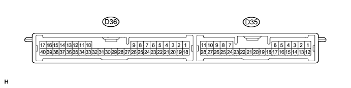
Measure the resistance and voltage according to the value(s) in the table below.
Tester Connection Wiring Color Terminal Description Condition Specified Condition D35-24 (HSW) - Body ground R - Body ground Engine hood courtesy switch Engine hood CLOSED (OFF) → OPEN (ON) Below 1 Ω → 10 kΩ or higher D36-1 (+B) - D36-17 (E) B - B Battery power supply Always 11 to 14 V D36-17 (E) - Body ground B - Body ground Ground Always Below 1 Ω If the result is not as specified, there may be a malfunction on the wire harness side.
-
Reconnect the D35 and D36 ECU connectors.
-
Measure the voltage according to the value(s) in the table below.
Tester Connection Wiring Color Terminal Description Condition Specified Condition D35-20 (SH-) - Body ground W - Body ground Security horn drive Security horn is sounding (Theft deterrent system is in alarm sounding state) Pulse generation
(Below 1 V ← → 12 V)
D36-2 (IND) - Body ground W - Body ground Security indicator light output Security indicator light is on (It comes on only in alarm sounding state. It flashes when immobiliser is operating.) 3 to 6 V If the result is not as specified, the certification ECU (smart key ECU assembly) may have a malfunction.
-