THEFT DETERRENT SYSTEM (w/o Smart Entry and Start System) ECU Power Source Circuit
DESCRIPTION
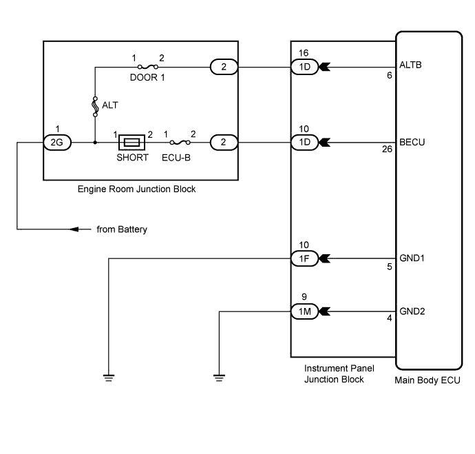
This circuit provides power for main body ECU operation.
WIRING DIAGRAM
INSPECTION PROCEDURE
PROCEDURE
-
CHECK INSTRUMENT PANEL JUNCTION BLOCK (MAIN BODY ECU (POWER SOURCE))
-
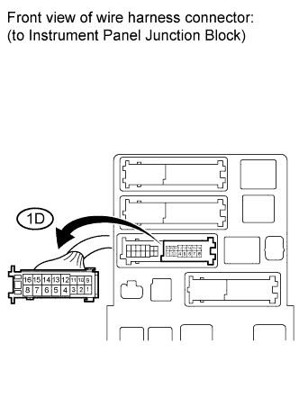
Disconnect the 1D junction block connector.
-
Measure the voltage according to the value(s) in the table below.
Standard voltage Tester Connection Specified Condition 1D-10 - Body ground 11 to 14 V 1D-16 - Body ground 11 to 14 V
NG 
REPAIR OR REPLACE HARNESS OR CONNECTOR
OK 
-
-
CHECK HARNESS AND CONNECTOR (INSTRUMENT PANEL JUNCTION BLOCK - BODY GROUND)
-
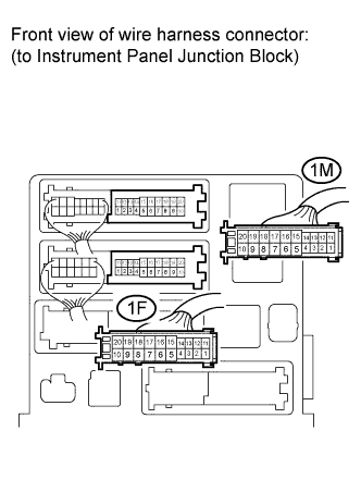
Disconnect the 1F and 1M junction block connectors.
-
Measure the resistance according to the value(s) in the table below.
Standard resistance Tester Connection Specified Condition 1F-10 - Body ground Below 1 Ω 1M-9 - Body ground Below 1 Ω
NG
REPAIR OR REPLACE HARNESS OR CONNECTOR
OK 
PROCEED TO NEXT CIRCUIT INSPECTION SHOWN IN PROBLEM SYMPTOMS TABLE Click here
-