| DTC Code | DTC Name |
|---|---|
| Front Passenger Side Seat Belt Warning Light Malfunction |
DESCRIPTION
When the passenger seat belt is not fastened with the ignition switch on (IG) and the passenger seat occupied, the passenger seat belt warning light display blinks. The occupant detection sensor detects if the passenger seat is occupied and sends signals to the combination meter assembly. After receiving the signals from the occupant detection sensor and inner belt, the combination meter assembly sends signals to the navigation receiver assembly*1 or hazard warning switch*2 to request the passenger seat belt warning light to blink or go off.
-
*1: w/ Navigation System
-
*2: w/o Navigation System
INSPECTION PROCEDURE
PROCEDURE
- Click here
PERFORM ACTIVE TEST USING INTELLIGENT TESTER
-
Connect the intelligent tester to the DLC3.
-
Turn the ignition switch on (IG).
-
Read the DATA LIST according to the displays on the tester screen.
Table 1. Combination Meter Tester Display Test Part Control Range Diagnostic Note Front Passenger Side Seat Belt Front passenger side seat belt warning light Front passenger side seat belt warning light is OFF / ON Confirm that the vehicle is stopped with engine idling
- OKClick here
- NGClick here
-
- Click here
CHECK HARNESS AND CONNECTOR
-
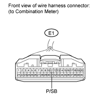
Disconnect the E1 connector from the combination meter.
-
Measure the resistance according to the value(s) in the table below.
Standard resistance Tester Connection Switch Condition Specified Condition E1-11 (P/SB) - Body ground Passenger seat occupied and buckle switch is on Below 100 Ω
- OKClick here
- NGClick here
-
- Click here
CHECK HARNESS AND CONNECTOR (BATTERY - NAVIGATION RECEIVER OR HAZARD WARNING LIGHT)
-
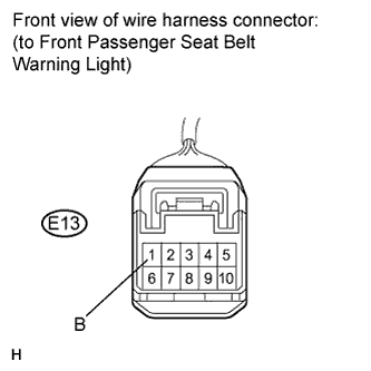
Disconnect E13 connector from the navigation receiver.*1
-
Disconnect E13 connector from the hazard warning switch.*2
-
Measure the voltage according to the value(s) in the table below.
Standard voltage Tester Connection Switch Condition Specified Condition E13-1 (B) - Body ground Ignition switch on (IG) 11 to 14 V Tip:
-
*1: w/ Navigation System
-
*2: w/o Navigation System
-
- OKClick here
- NGClick here
-
- Click here
CHECK HARNESS AND CONNECTOR (NAVIGATION RECEIVER OR HAZARD WARNING LIGHT - BODY GROUND)
-
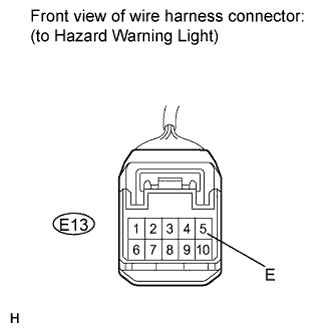
Measure the resistance according to the value(s) in the table below.
Standard resistance Tester Connection Switch Condition Specified Condition E13-5 (E) - Body ground Always Below 1 Ω
- OKClick here
- NGClick here
-
- Click here
CHECK HARNESS AND CONNECTOR
-
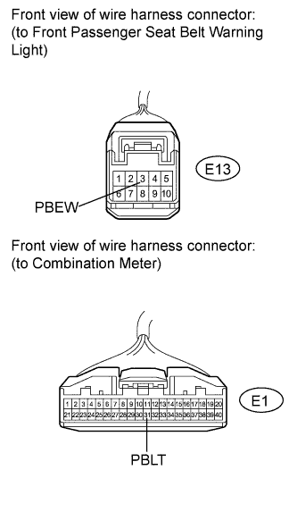
Measure the resistance according to the value(s) in the table below.
Standard resistance Tester Connection Switch Condition Specified Condition E1-31 (PBLT) - E13-3 (PBEW) Always Below 1 Ω E1-31 (PBLT) or E13-3 (PBEW) - Body ground Always 10 kΩ or higher -
Proceed to the next step based on the inspection result.
Result Result Proceed to OK (w/Navigation system) A OK (w/o Navigation system) B NG C
-
- Click here
CHECK HARNESS AND CONNECTOR (COMBINATION METER - FRONT SEAT INNER BELT)
-
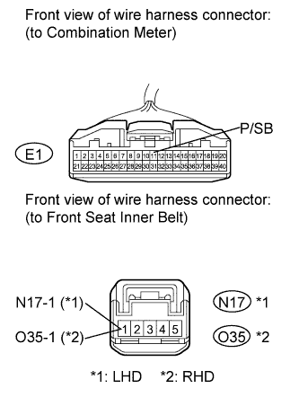
Disconnect N17 connector from the front seat inner belt RH.*1
-
Disconnect O35 connector from the front seat inner belt LH.*2
-
Measure the resistance according to the value(s) in the table below.
Standard resistance Tester Connection Switch Condition Specified Condition E1-11 (P/SB) - N17-1*1
E1-11 (P/SB) - O35-1*2
Always Below 1 Ω E1-11 (P/SB) or N17-1 - Body ground*1
E1-11 (P/SB) or O35-1 - Body ground*2
Always 10 kΩ or higher Tip:
-
*1: LHD
-
*2: RHD
-
- OKClick here
- NGClick here
-
- Click here
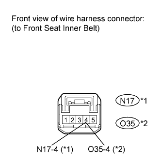
CHECK HARNESS AND CONNECTOR (FRONT SEAT INNER BELT - BODY GROUND)
-
Measure the resistance according to the value(s) in the table below.
Standard resistance Tester Connection Switch Condition Specified Condition N17-4 - Body ground*1
O35-4 - Body ground*2
Always Below 1 Ω Tip:
-
*1: LHD
-
*2: RHD
-
- OKClick here
- NGClick here
-
- Click here
INSPECT OCCUPANT DETECTION SENSOR
-
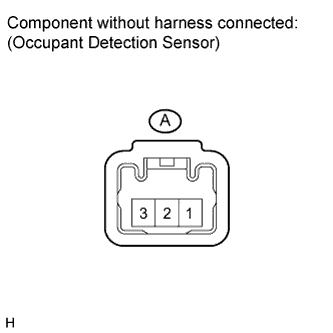
Disconnect A connector from the occupant detection sensor.
-
Measure the resistance according to the value(s) in the table below.
Standard resistance Tester Connection Condition Specified Condition A-1 - A-3 Passenger seat is occupied Below 100 Ω A-1 - A-3 Passenger seat is not occupied 1 MΩ or higher
- OKClick here
- NGClick here
-
- Click here
REPLACE COMBINATION METERClick here
- Click here
REPAIR OR REPLACE HARNESS OR CONNECTOR, OR REPLACE FUSE
- Click here
REPAIR OR REPLACE HARNESS OR CONNECTOR
- Click here
REPLACE NAVIGATION RECEIVERClick here
- Click here
REPLACE HAZARD WARNING SWITCHClick here
- Click here
REPAIR OR REPLACE HARNESS OR CONNECTOR
- Click here
REPAIR OR REPLACE HARNESS OR CONNECTOR (COMBINATION METER - FRONT SEAT INNER BELT)
- Click here
REPAIR OR REPLACE HARNESS OR CONNECTOR (FRONT SEAT INNER BELT - BODY GROUND)
- Click here
REPLACE OCCUPANT DETECTION SENSOR
- Click here
REPLACE FRONT SEAT INNER BELT (PASSENGER SIDE)Click here