DRIVER SIDE KNEE AIRBAG ASSEMBLY INSTALLATION
-
INSTALL DRIVER SIDE KNEE AIRBAG ASSEMBLY
-
Check that the ignition switch is off.
-
Check that the battery negative (-) cable is disconnected.
CAUTION:
Wait for at least 90 seconds after disconnecting the cable to prevent airbag deployment.
-
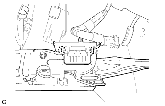
Install the DLC3 to the driver side knee airbag assembly with the 2 claws.
-
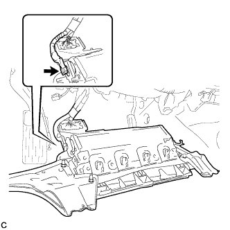
Connect the connector to the driver side knee airbag assembly.
Note
When handling the airbag connector, take care not to damage the airbag wire harness.
-
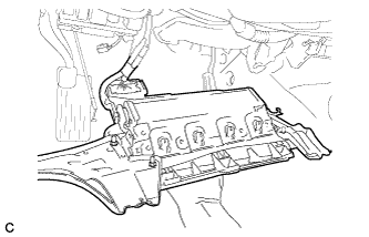
Support the driver side knee airbag assembly with one hand as shown in the illustration.
-
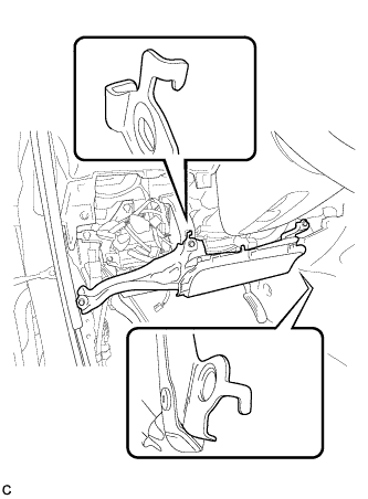
Temporarily install the driver side knee airbag assembly with the 2 hooks.
-
Install the driver side knee airbag assembly with the 4 bolts.
- Torque:
- 10 N*m { 102 kgf*cm, 7 ft.*lbf }
-
-
INSTALL LOWER INSTRUMENT PANEL FINISH PANEL SUB-ASSEMBLY (for Manual Air Conditioning System)
-

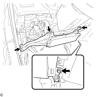
Connect the hood lock control cable assembly.
-
Connect each connector.
-
Engage the 3 claws and 10 clips.
-
Install the lower instrument panel finish panel sub-assembly with the 2 bolts <B>.
-
-
INSTALL LOWER INSTRUMENT PANEL FINISH PANEL SUB-ASSEMBLY (for Automatic Air Conditioning System)
-

Connect the hood lock control cable assembly.
-
Connect each connector and the aspirator duct.
-

Engage the 3 claws and 10 clips.
-
Install the lower instrument panel finish panel sub-assembly with the 2 bolts <B>.
-
-
INSTALL COWL SIDE TRIM SUB-ASSEMBLY LH
-

Engage the claw and clip, install the cowl side trim sub-assembly LH.
-
Install the clip.
-
-
INSTALL FRONT DOOR SCUFF PLATE LH
-

Engage the guide and the 8 claws, and install the front door scuff plate LH.
-
-
CONNECT CABLE TO NEGATIVE BATTERY TERMINAL
Note
When disconnecting the cable, some systems need to be initialized after the cable is reconnected Click here.
-
INSPECT SRS WARNING LIGHT
-
Inspect the SRS warning light Click here.
-