SOLAR SENSOR INSPECTION
-
INSPECT SOLAR SENSOR
-
Remove the A/C solar sensor with the connector still connected.
-
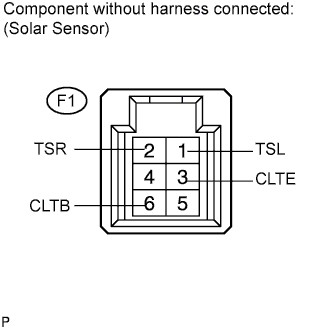
Apply battery voltage between terminals 6 (CLTB) and 3 (CLTE) of the A/C solar sensor.
-
Measure the voltage according to the value(s) in the table below.
Standard voltage Tester Connection Condition Specified Condition F1-1 (TSR) - F1-3 (CLTE) Sensor is subjected to electric light 0.8 to 4.3 V F1-1 (TSR) - F1-3 (CLTE) Sensor is covered with a cloth Below 0.8 V F1-2 (TSR) - F1-3 (CLTE) Sensor is subjected to electric light 0.8 to 4.3 V F1-2 (TSR) - F1-3 (CLTE) Sensor is covered with a cloth Below 0.8 V Note
-
The connection procedure for using a digital tester such as a TOYOTA electrical tester is shown above. When using an analog tester, connect the positive (+) lead to terminal 2 and negative (-) lead to terminal 1 of the solar sensor.
-
While using the battery during inspection, do not bring the positive and negative tester probes too close to each other as a short circuit may occur.
Tech Tips
-
Use an incandescent light for inspection. Bring it within about 30 cm (11.8 in.) of the solar sensor.
-
As the inspection light is moved away from the sensor, the voltage decreases.
-
-