FRONT EVAPORATOR TEMPERATURE SENSOR REMOVAL
-
PRECAUTION
-
RECOVER REFRIGERANT FROM REFRIGERATION SYSTEM
-
Start the engine.
-
Turn the A/C switch on.
-
Operate the cooler compressor at an engine speed of approximately 1000 rpm for 5 to 6 minutes to circulate the refrigerant. This causes most of the compressor oil from the various components of the A/C system to collect in the A/C compressor.
-
Stop the engine.
-
Recover the refrigerant from the A/C system using a refrigerant recovery unit.
-
-
POSITION FRONT WHEELS STRAIGHT AHEAD
-
DISCONNECT CABLE FROM NEGATIVE BATTERY TERMINAL
CAUTION:
Wait for 90 seconds after disconnecting the cable to prevent the airbag from deploying Click here.
Note
When disconnecting the cable, some systems need to be initialized after the cable is reconnected Click here.
-
REMOVE FRONT WIPER ARM AND BLADE ASSEMBLY LH
-
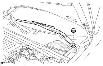
Remove the nut, and the front wiper arm and blade assembly LH.
-
-
REMOVE FRONT WIPER ARM AND BLADE ASSEMBLY RH
-
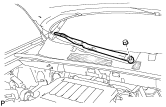
Remove the nut, and the front wiper arm and blade assembly RH.
-
-
REMOVE COWL TOP VENTILATOR LOUVER SUB-ASSEMBLY
-
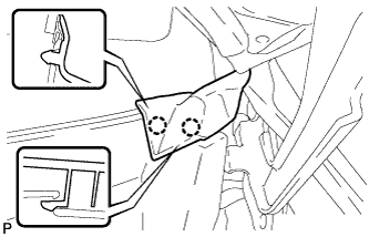
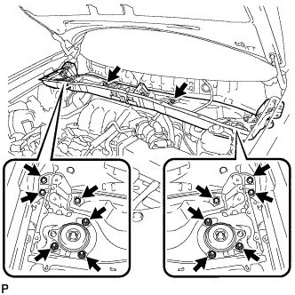
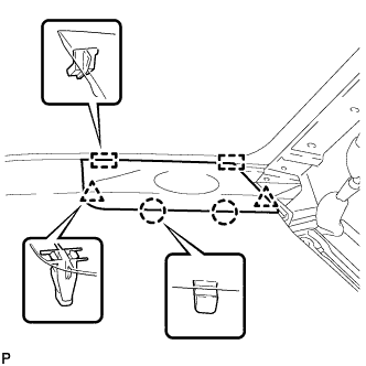
Disengage the 2 claws and disconnect the front fender to cowl side seal LH.
-
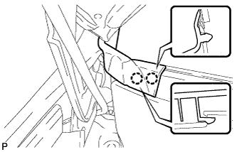
Disengage the 2 claws and disconnect the front fender to cowl side seal RH.
-
Remove the 2 clips.
-
Disengage the 20 claws and remove the cowl top ventilator louver sub-assembly.
-
-
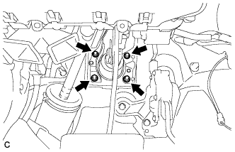
REMOVE WINDSHIELD WIPER MOTOR AND LINK ASSEMBLY
-
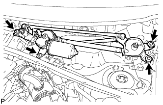
Disconnect the connector.
-
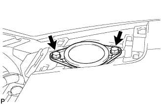
Remove the 4 bolts, and the windshield wiper motor and link assembly.
-
-
REMOVE COWL TOP OUTER PANEL SUB-ASSEMBLY
-
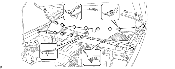
Disengage the 4 clamps and separate the wiper wire harness from the outer cowl top panel sub-assembly.
-
Remove the 8 bolts, 6 nuts, and the outer cowl top panel sub-assembly.
-
-
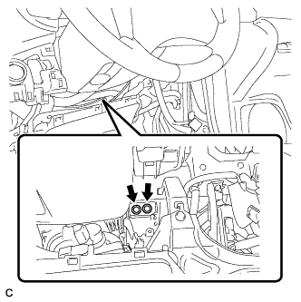
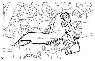
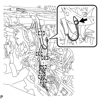
DISCONNECT HEATER WATER HOSE OUTLET
-
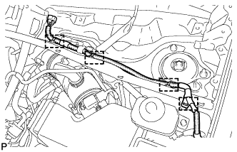
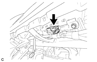
Using pliers, grip the claws of the clip and slide the clip to disconnect the heater outlet water hose.
Note
-
Do not apply excessive force to the heater outlet water hose.
-
Prepare a drain pan or cloth in case the coolant leaks.
-
-
-
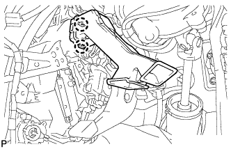
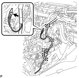
DISCONNECT HEATER WATER HOSE INLET
-
Using pliers, grip the claws of the clip and slide the clip to disconnect the heater inlet water hose.
Note
-
Do not apply excessive force to the heater inlet water hose.
-
Prepare a drain pan or cloth in case the coolant leaks.
-
-
-
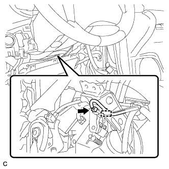
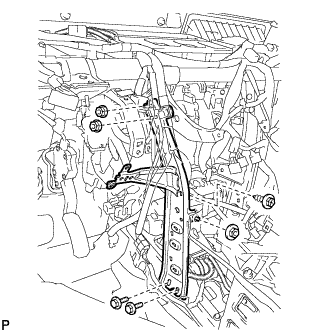
DISCONNECT COOLER REFRIGERANT LIQUID PIPE A
-
Remove the bolt, and slide the hook connector.
-
Disconnect the cooler refrigerant liquid pipe A.
-
Remove the O-ring from the cooler refrigerant liquid pipe A.
Note
Seal the openings of the disconnected parts using vinyl tape to prevent entry of moisture and foreign matter.
-
-
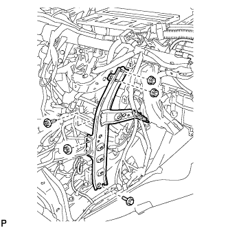
DISCONNECT NO. 1 COOLER REFRIGERANT SUCTION PIPE
-
Disconnect the No. 1 cooler refrigerant suction pipe.
-
Remove the O-ring from the No. 1 cooler refrigerant suction pipe.
Note
Seal the openings of the disconnected parts using vinyl tape to prevent entry of moisture and foreign matter.
-
-
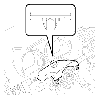
REMOVE LOWER NO. 3 STEERING WHEEL COVER
-
Disengage the claw and remove the lower No. 3 steering wheel cover.
-
-
REMOVE LOWER NO. 2 STEERING WHEEL COVER
-
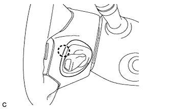
Disengage the claw and remove the lower No. 2 steering wheel cover.
-
-
REMOVE STEERING PAD
-
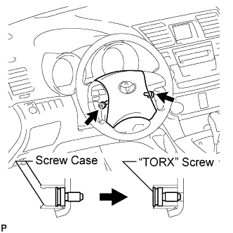
Using a "TORX" socket wrench (T30), loosen the 2 "TORX" screws until the groove along the screw circumference catches on the screw case.
-
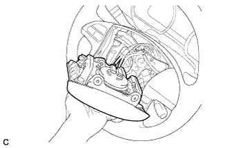
Pull out the steering pad from the steering wheel assembly and support the steering pad with one hand as shown in the illustration.
Note
When removing the steering pad, do not pull the airbag wire harness.
-
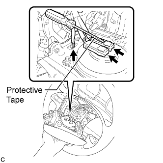
Disconnect the horn connector from the steering pad.
-
Using a screwdriver with the tip wrapped with protective tape, disconnect the 2 airbag connectors and remove the steering pad.
Note
When handling the airbag connector, take care not to damage the airbag wire harness.
-
-
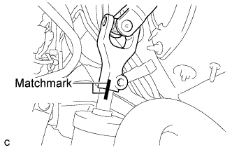
REMOVE STEERING WHEEL ASSEMBLY
-
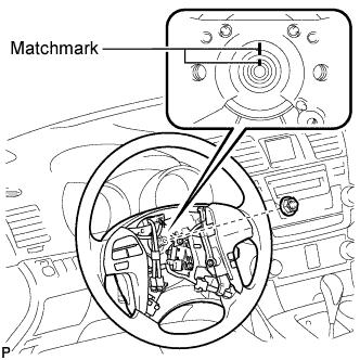
Remove the steering wheel assembly set nut.
-
Put matchmarks on the steering wheel assembly and the steering main shaft.
-
Disconnect the connectors from the spiral cable.
-
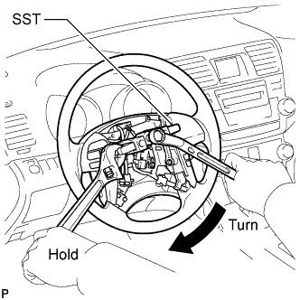
Using SST, remove the steering wheel assembly.
- SST
- 09950-50013 ( 09951-05010, 09952-05010, 09953-05020, 09954-05021 )
Note
Apply a small amount of grease to the threads and tip of SST (09953-05020) before use.
-
-
REMOVE STEERING COLUMN COVER
-
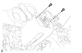
Remove the 2 screws.
-
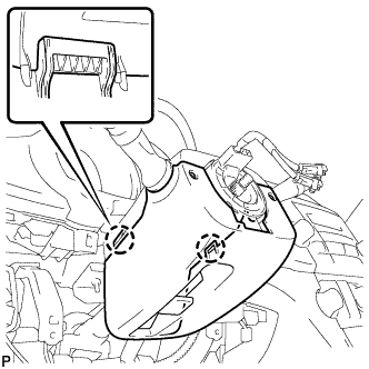
Disengage the 2 claws to remove the lower steering column cover.
-
Disengage the claw to remove the upper steering column cover.
-
-
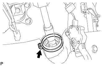
REMOVE TURN SIGNAL SWITCH ASSEMBLY WITH SPIRAL CABLE SUB-ASSEMBLY
-
Disconnect the connectors from the turn signal switch assembly with spiral cable sub-assembly.
-
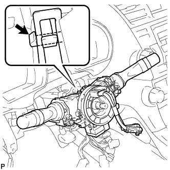
Using pliers, grip the claws of the clip and remove the turn signal switch assembly with spiral cable sub-assembly.
-
-
REMOVE INSTRUMENT CLUSTER FINISH PANEL ASSEMBLY
-
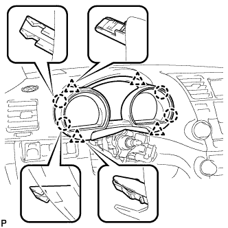
Disengage the 4 claws and 4 clips, and remove the instrument cluster finish panel assembly.
-
-
REMOVE COMBINATION METER ASSEMBLY
-
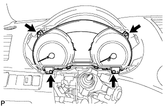
Remove the 4 screws <F>.
-
Disconnect the connector and remove the combination meter assembly.
-
-
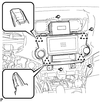
REMOVE CENTER INSTRUMENT PANEL REGISTER ASSEMBLY
-
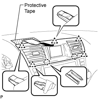
Apply protective tape to the areas shown in the illustration.
-
Using a moulding remover, disengage the 2 claws and 5 clips, and then remove the center instrument panel register assembly as shown in the illustration.
-
-
REMOVE CENTER INSTRUMENT CLUSTER FINISH PANEL ASSEMBLY (w/o Smart Entry and Start System)
-
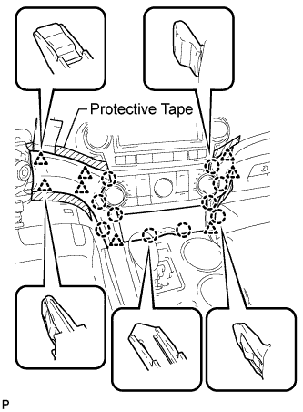
Apply protective tape to the areas shown in the illustration.
-
Using a moulding remover, disengage the 10 claws and 8 clips starting from the upper part of the center instrument cluster finish panel assembly.
Note
Do not pull on the small storage compartment lid. Doing so may cause damage.
-
Disconnect each connector and remove the center instrument cluster finish panel assembly.
-
-
REMOVE CENTER INSTRUMENT CLUSTER FINISH PANEL ASSEMBLY (w/ Smart Entry and Start System)
-
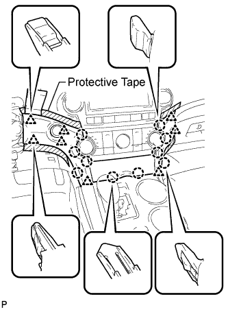
Apply protective tape to the areas shown in the illustration.
-
Using a moulding remover, disengage the 10 claws and 8 clips starting from the upper part of the center instrument cluster finish panel assembly.
Note
Do not pull on the small storage compartment lid. Doing so may cause damage.
-
Disconnect each connector and remove the center instrument cluster finish panel assembly.
-
-
REMOVE HEATER CONTROL AND ACCESSORY ASSEMBLY (for Manual Air Conditioning System)
-

Disengage the 4 clips and remove the heater control and accessory assembly.
-
Disconnect the connector.
-
-
REMOVE AIR CONDITIONING CONTROL ASSEMBLY (for Automatic Air Conditioning System)
-
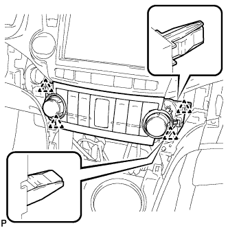
Disengage the 4 clips and remove the air conditioning control assembly.
-
Disconnect the connector.
-
-
REMOVE RADIO RECEIVER ASSEMBLY WITH BRACKET (w/o Navigation System)
-
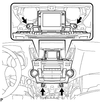
Remove the 4 bolts.
-
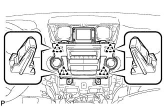
Pull the radio receiver assembly with bracket toward the rear of the vehicle and disengage the 4 clips.
-
Disconnect each connector and remove the radio receiver assembly with bracket.
-
-
REMOVE NAVIGATION RECEIVER ASSEMBLY WITH BRACKET (w/ Navigation System)
-
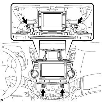
Remove the 4 bolts.
-
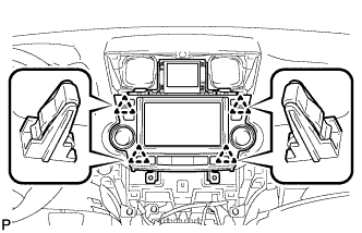
Pull the navigation receiver assembly with bracket toward the rear of the vehicle and disengage the 4 clips.
-
Disconnect each connector and remove the navigation receiver assembly with bracket.
-
-
REMOVE INTEGRATION CONTROL AND PANEL ASSEMBLY WITH BRACKET (w/o Radio Receiver)
-
Remove the 4 bolts <D>.
-
Disengage the 4 clips.
-
Disconnect each connector and remove the integration control and panel assembly with bracket.
-
-
REMOVE FRONT DOOR SCUFF PLATE LH
-

Disengage the 8 claws and guide, and remove the front door scuff plate LH.
-
-
REMOVE COWL SIDE TRIM SUB-ASSEMBLY LH
-

Remove the clip.
-
Disengage the clip and claw, and remove the cowl side trim sub-assembly LH.
-
-
REMOVE LOWER INSTRUMENT PANEL FINISH PANEL SUB-ASSEMBLY (for Manual Air Conditioning System)
-

Remove the 2 bolts <B>.
-
Disengage the 3 claws and 10 clips.
-
Disconnect each connector.
-
Disconnect the hood lock control cable assembly and remove the lower instrument panel finish panel sub-assembly.
-
-
REMOVE LOWER INSTRUMENT PANEL FINISH PANEL SUB-ASSEMBLY (for Automatic Air Conditioning System)
-

Remove the 2 bolts <B>.
-
Disengage the 3 claws and 10 clips.
-

Disconnect each connector and the aspirator duct.
-
Disconnect the hood lock control cable assembly and remove the lower instrument panel finish panel sub-assembly.
-
-
REMOVE FRONT DOOR SCUFF PLATE RH
Tech Tips
Use the same procedure for the RH side and the LH side.
-
REMOVE COWL SIDE TRIM SUB-ASSEMBLY RH
Tech Tips
Use the same procedure for the RH side and the LH side.
-
REMOVE NO. 2 INSTRUMENT PANEL UNDER COVER SUB-ASSEMBLY
-
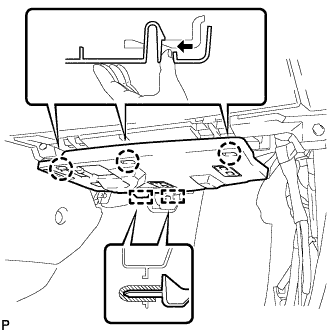
Disengage the 3 claws.
-
Disengage the 2 guides and remove the No. 2 instrument panel under cover sub-assembly.
-
-
REMOVE LOWER INSTRUMENT PANEL SUB-ASSEMBLY
-
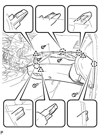
Remove the 2 bolts <B> and 3 screws <F>.
-
Disengage the 4 claws and 3 clips.
-
Disconnect each connector and clamp, and remove the lower instrument panel sub-assembly.
-
-
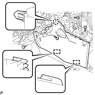
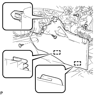
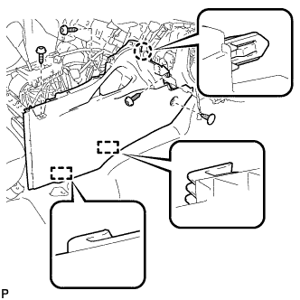
REMOVE UPPER CONSOLE PANEL SUB-ASSEMBLY
-
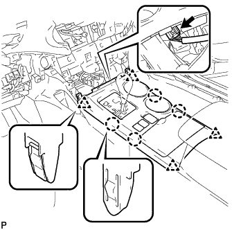
Disengage the 4 claws and 4 clips.
-
Disconnect the connector and remove the upper console panel sub-assembly.
-
-
REMOVE NO. 2 CONSOLE BOX DUCT (w/o Rear Air Conditioning System)
-
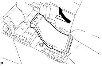
Remove the No. 2 console box duct as shown in the illustration.
-
-
REMOVE LOWER REAR CONSOLE BOX
-
Remove the lower rear console box.
-
-
REMOVE CONSOLE BOX ASSEMBLY (w/o Rear Air Conditioning System)
-
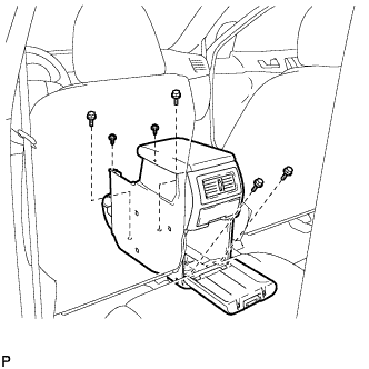
Remove the 4 bolts and 2 screws.
-
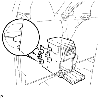
Disengage the 6 claws and remove the console box assembly.
-
-
REMOVE CONSOLE BOX ASSEMBLY (w/ Rear Air Conditioning System)
-
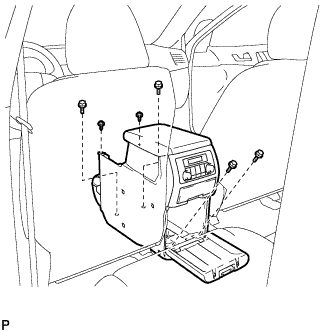
Remove the 4 bolts and 2 screws.
-
Disconnect the connector.
-
Disengage the 6 claws, and remove the console box assembly.
-
-
REMOVE FRONT NO. 1 CONSOLE BOX INSERT (for LHD)
-
Using a clip remover, remove the 2 clips.
-
Remove the 3 screws <F>.
-
Disengage the claw and 2 guides, and then remove the front No. 1 console box insert.
-
-
REMOVE FRONT NO. 1 CONSOLE BOX INSERT (for RHD)
-
Using a clip remover, remove the clip.
-
Remove the 3 screws <F>.
-
Disengage the claw and 2 guides, and then remove the front No. 1 console box insert.
-
-
REMOVE FRONT NO. 2 CONSOLE BOX INSERT (for LHD)
-
Using a clip remover, remove the clip.
-
Remove the 3 screws <F>.
-
Disengage the claw and 2 guides, and then remove the front No. 2 console box insert.
-
-
REMOVE FRONT NO. 2 CONSOLE BOX INSERT (for RHD)
-
Using a clip remover, remove the clip.
-
Remove the 3 screws <F>.
-
Disengage the claw and 2 guides, and then remove the front No. 2 console box insert.
-
-
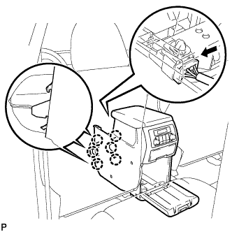
REMOVE ENGINE SWITCH (w/ Smart Entry and Start System)
-
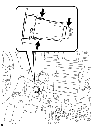
Disconnect the switch connector.
-
Disengage the 2 claws and remove the switch.
-
-
DISCONNECT FRONT DOOR OPENING TRIM WEATHERSTRIP LH
-
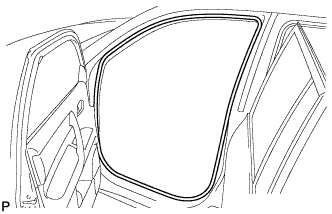
Remove the front door opening trim weatherstrip LH.
-
-
REMOVE FRONT PILLAR GARNISH LH
-
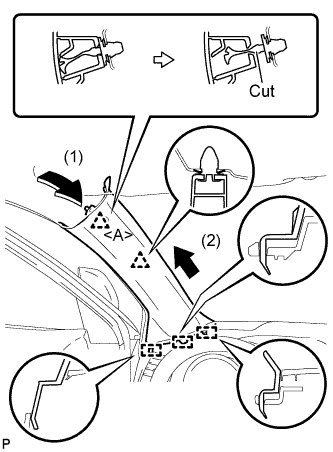
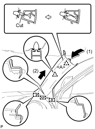
Pull the upper part of the garnish toward the inside of the cabin and disengage the 2 clips.
-
Cut off the clip <A>.
-
Disengage the 3 guides and remove the front pillar garnish LH.
-
Remove the clip <A>.
-
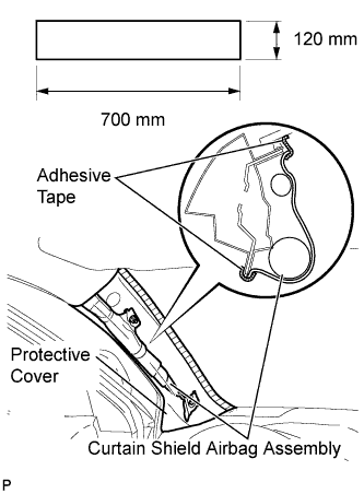
Protect the curtain shield airbag assembly.
-
Cover the airbag with a 700 mm (27.56 in.) x 120 mm (4.72 in.) cloth or piece of nylon and fix the ends of the cover with tape, as shown in the illustration.
Note
Cover the curtain shield airbag with a protective cover as soon as the front pillar garnish is removed.
-
-
-
DISCONNECT FRONT DOOR OPENING TRIM WEATHERSTRIP RH
Tech Tips
Use the same procedure for the RH side and the LH side.
-
REMOVE FRONT PILLAR GARNISH RH
-
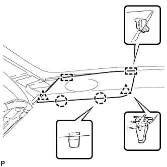
Pull the upper part of the garnish toward the inside of the cabin and disengage the 2 clips.
-
Cut off the clip <A>.
-
Disengage the 3 guides and remove the front pillar garnish RH.
-
Remove the clip <A>.
-
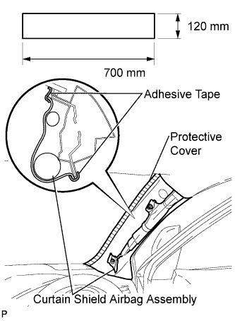
Protect the curtain shield airbag assembly.
-
Cover the airbag with a 700 mm (27.56 in.) x 120 mm (4.72 in.) cloth or piece of nylon and fix the ends of the cover with tape, as shown in the illustration.
Note
Cover the curtain shield airbag with a protective cover as soon as the front pillar garnish is removed.
-
-
-
REMOVE NO. 1 INSTRUMENT PANEL SPEAKER PANEL SUB-ASSEMBLY
-
Disengage the 2 claws and 2 clips.
-
Disengage the 2 guides and remove the No. 1 instrument panel speaker panel sub-assembly.
-
-
REMOVE FRONT NO. 2 SPEAKER ASSEMBLY (for LH Side)
-
Remove the 2 bolts and front No. 2 speaker assembly.
-
Disconnect the connector.
-
-
REMOVE NO. 2 INSTRUMENT PANEL SPEAKER PANEL SUB-ASSEMBLY
-
Disengage the 2 claws and 2 clips.
-
Disengage the 2 guides and remove the No. 2 instrument panel speaker panel sub-assembly.
-
-
REMOVE FRONT NO. 2 SPEAKER ASSEMBLY (for RH Side)
Tech Tips
Use the same procedures for the RH side and the LH side.
-
DISCONNECT INSTRUMENT PANEL WIRE ASSEMBLY
-
Disconnect the connector.
-
-
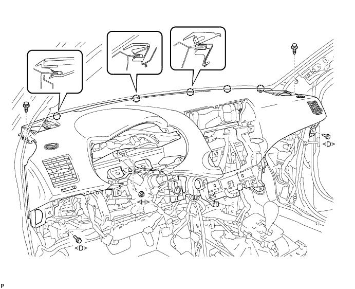
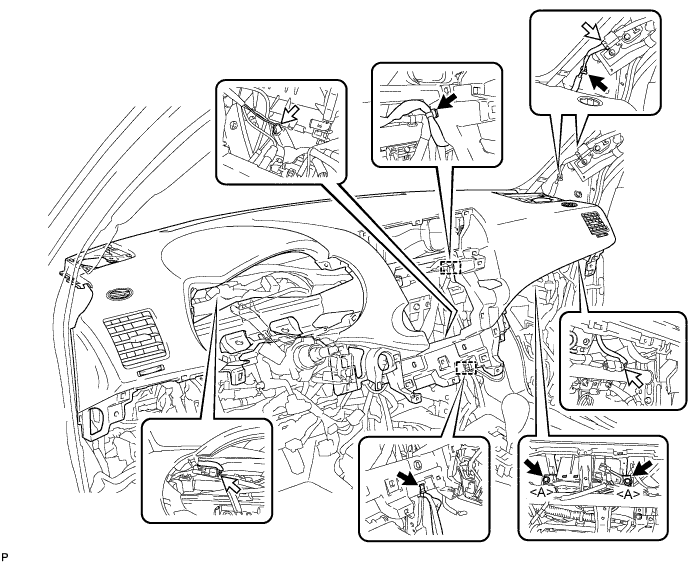
REMOVE INSTRUMENT PANEL SAFETY PAD ASSEMBLY (for Pole Antenna Type)
-
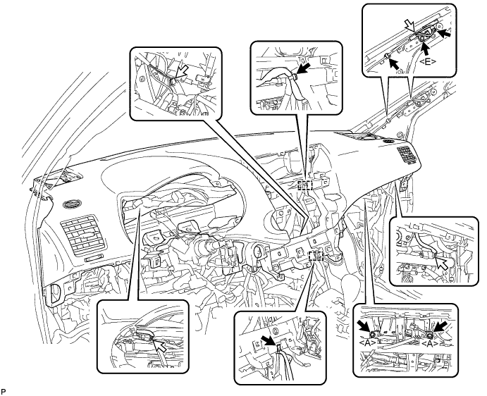
Disconnect each connector.
-
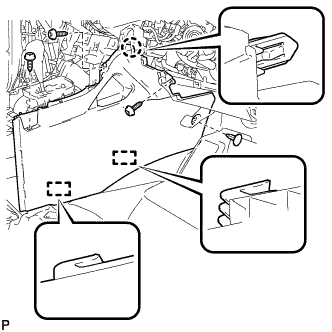
Remove the bolt <E>.
-
Remove the 2 passenger airbag bolts <A>.
-
Disengage each clamp.
-
Remove the 2 clips.
-
Remove the 2 bolts <D> and nut <H>.
-
Disengage the 5 claws and remove the instrument panel safety pad assembly.
-
-
REMOVE INSTRUMENT PANEL SAFETY PAD ASSEMBLY (for Glass Antenna Type)
-
Disconnect each connector.
-
Remove the 2 passenger airbag bolts <A>.
-
Disengage each clamp.
-
Remove the 2 clips.
-
Remove the 2 bolts <D> and nut <H>.
-
Disengage the 5 claws and remove the instrument panel safety pad assembly.
-
-
REMOVE BRAKE PEDAL RETURN SPRING
-
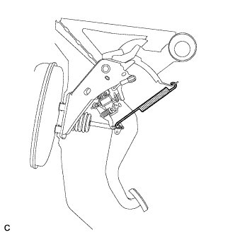
Remove the brake pedal return spring from the push rod pin and instrument panel reinforcement.
-
-
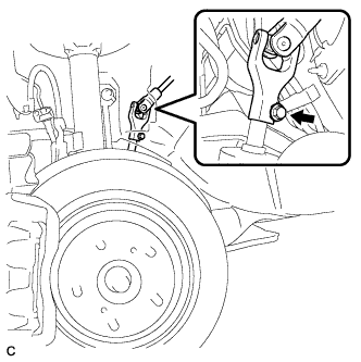
REMOVE STOP LIGHT SWITCH ASSEMBLY
-
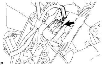
Disconnect the connector.
-
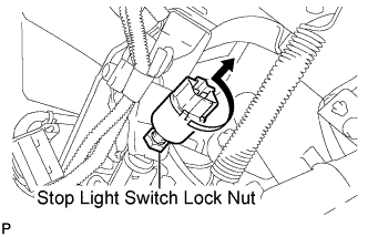
Loosen the stop light switch lock nut.
-
Remove the stop light switch assembly as shown in the illustration.
-
-
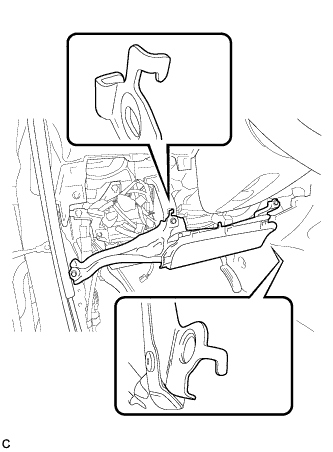
SEPARATE BRAKE MASTER CYLINDER PUSH ROD CLEVIS
-
Remove the clip and push rod pin, and separate the brake master cylinder push rod clevis from the brake pedal sub-assembly.
-
-
REMOVE BRAKE PEDAL SUPPORT SUB-ASSEMBLY (for LHD)
-
Disconnect the brake pedal load sensing switch connector and disengage the clamp.
-
Remove the 2 bolts and separate the brake pedal support sub-assembly from the instrument panel reinforcement.
-
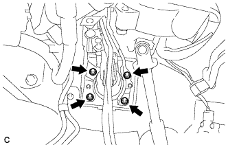
Remove the 4 nuts and brake pedal support sub-assembly from the body.
-
-
REMOVE BRAKE PEDAL SUPPORT SUB-ASSEMBLY (for RHD)
-
Disconnect the brake pedal load sensing switch connector and disengage the clamp.
-
Remove the 2 bolts and separate the brake pedal support sub-assembly from the instrument panel reinforcement.
-
Remove the 4 nuts and brake pedal support sub-assembly from the body.
-
-
REMOVE DRIVER SIDE KNEE AIRBAG ASSEMBLY
-
Remove the 4 bolts.
-
Disengage the 2 hooks.
-
Pull out the driver side knee airbag assembly from the vehicle and support the driver side knee airbag assembly with one hand as shown in the illustration.
Note
When removing the driver side knee airbag assembly, do not pull the airbag wire harness.
-
Using a screwdriver with the tip wrapped with protective tape, disconnect the driver side knee airbag connector.
Note
When handling the airbag connector, take care not to damage the airbag wire harness.
-
Disengage the 2 claws and separate the DLC3 from the driver side knee airbag assembly.
-
-
REMOVE NO. 1 AIR DUCT SUB-ASSEMBLY (for LHD)
-
Disengage the 2 claws and remove the No. 1 air duct sub-assembly.
-
-
REMOVE NO. 1 AIR DUCT SUB-ASSEMBLY (for RHD)
-
Disengage the 2 claws and remove the No. 1 air duct sub-assembly.
-
-
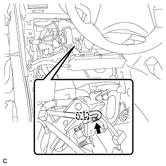
SEPARATE STEERING INTERMEDIATE SHAFT SUB-ASSEMBLY
-
Loosen the bolt.
-
Remove the bolt and slide the steering intermediate shaft sub-assembly.
Note
Do not separate the steering intermediate shaft sub-assembly from the power steering link assembly.
-
Put matchmarks on the steering intermediate shaft sub-assembly and the power steering link assembly.
-
Separate the steering intermediate shaft sub-assembly from the power steering link assembly.
-
-
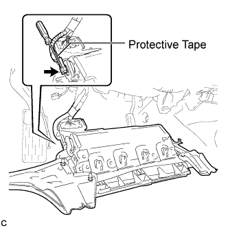
REMOVE STEERING COLUMN ASSEMBLY (for LHD)
-
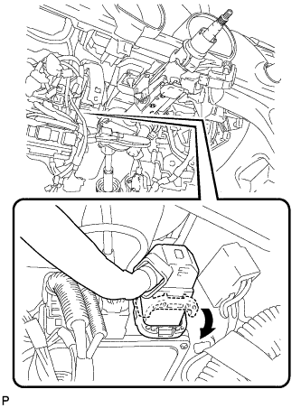
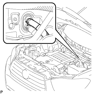
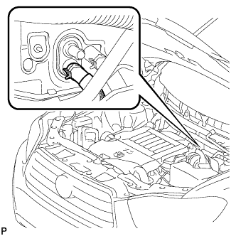
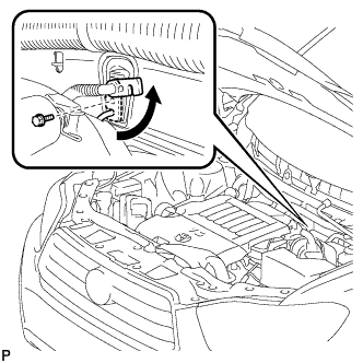
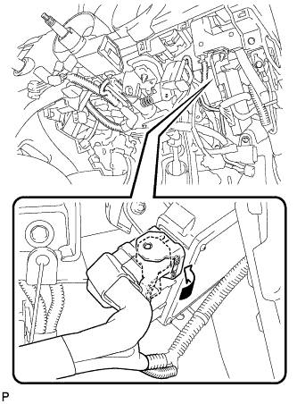
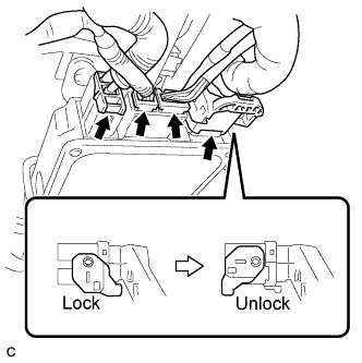
Disconnect the connector from the power steering ECU assembly.
Tech Tips
As shown in the illustration, turn the lock lever to disconnect the connector.
-
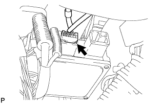
Disconnect the connector from the power steering ECU assembly.
-
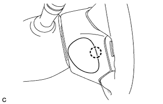
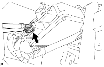
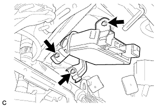
Disconnect the connectors and disengage the wire harness clamps from the steering column assembly.
-
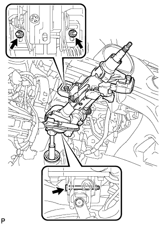
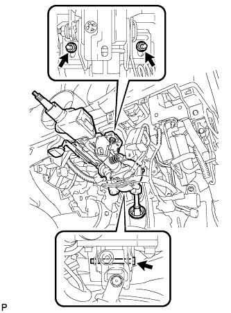
Remove the bolt, 2 nuts, and the steering column assembly.
-
-
REMOVE STEERING COLUMN ASSEMBLY (for RHD)
-
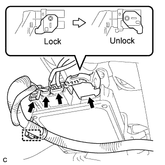
Disconnect the connector from the power steering ECU assembly.
Tech Tips
As shown in the illustration, turn the lock lever to disconnect the connector.
-
Disconnect the connector from the power steering ECU assembly.
-
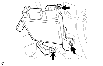
Disconnect the connectors and disengage the wire harness clamps from the steering column assembly.
-
Remove the bolt, 2 nuts, and the steering column assembly.
-
-
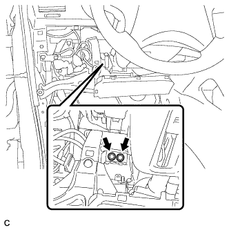
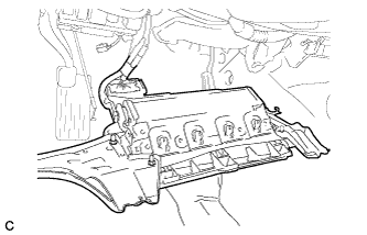
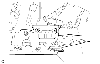
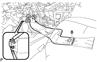
DISCONNECT INSTRUMENT PANEL JUNCTION BLOCK ASSEMBLY
-
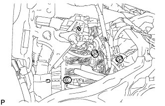
Remove the 3 nuts and disconnect the instrument panel junction block assembly.
-
-
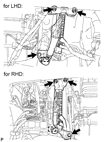
REMOVE POWER STEERING ECU ASSEMBLY (for LHD)
-
Disconnect the 4 connectors from the power steering ECU assembly.
-
Remove the 3 nuts and the power steering ECU assembly.
-
-
REMOVE POWER STEERING ECU ASSEMBLY (for RHD)
-
Separate the wire harness clamp from the power steering ECU assembly.
-
Disconnect the 4 connectors from the power steering ECU assembly.
-
Remove the 3 nuts and the power steering ECU assembly.
-
-
REMOVE ECM (for RHD)
-
Separate the harness connector (LHD).
-
Disconnect the 5 ECM connectors.
-
Remove the wire harness clamp.
-
Remove the 2 nuts, bolt and ECM.
-
-
REMOVE AIR CONDITIONING AMPLIFIER ASSEMBLY
-
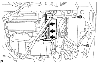
Disconnect each connector.
-
Remove the 2 screws and the air conditioning amplifier assembly.
-
-
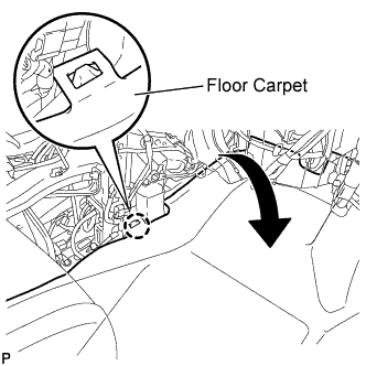
REMOVE REAR NO. 1 AIR DUCT
-
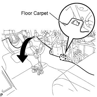
Disengage the claw.
-
Turn back the floor carpet as shown in the illustration.
-
Remove the clip.
-
Disengage the clamp.
-
Disengage the 2 claws and remove the rear No. 1 air duct.
-
-
REMOVE REAR NO. 3 AIR DUCT
-
Disengage the claw.
-
Turn back the floor carpet as shown in the illustration.
-
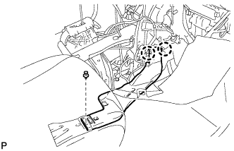
Remove the clip.
-
Disengage the 2 claws and remove the rear No. 3 air duct.
-
-
REMOVE NO. 1 CONSOLE BOX DUCT (w/o Rear Air Conditioning System)
-
Remove the clip and the No. 1 console box duct.
-
-
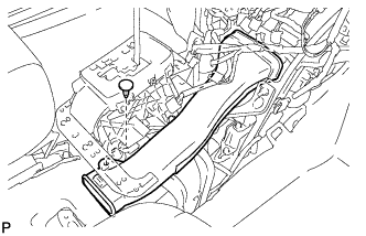
REMOVE CENTER HEATER TO REGISTER DUCT
-
Disengage the clamp.
-
Disengage the 4 claws and remove the center heater to register duct.
-
-
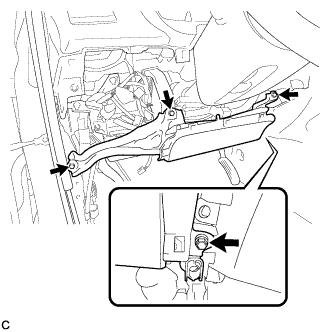
REMOVE NO. 1 INSTRUMENT PANEL BRACE SUB-ASSEMBLY
-
Remove the bolt and disconnect the earth wire.
-
Disengage each clamp.
-
Remove the 2 bolts.
-
Remove the screw.
-
Remove the 3 nuts and the No. 1 instrument panel brace sub-assembly.
-
-
REMOVE NO. 2 INSTRUMENT PANEL BRACE SUB-ASSEMBLY
-
Remove the bolt and disconnect the earth wire.
-
Disengage each clamp.
-
Remove the bolt.
-
Remove the screw.
-
Remove the 3 nuts and the No. 2 instrument panel brace sub-assembly.
-
-
REMOVE INSTRUMENT PANEL REINFORCEMENT ASSEMBLY WITH AIR CONDITIONING UNIT (w/o PTC Heater)
-
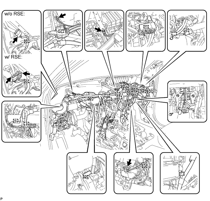
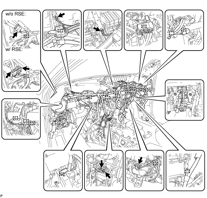
Disengage each clamp.
-
Remove the 2 bolts and disconnect the 2 earth wires.
-
Disconnect each connector.
-
Remove the 2 nuts and bolt.
-
Disconnect the blower motor connector.
-
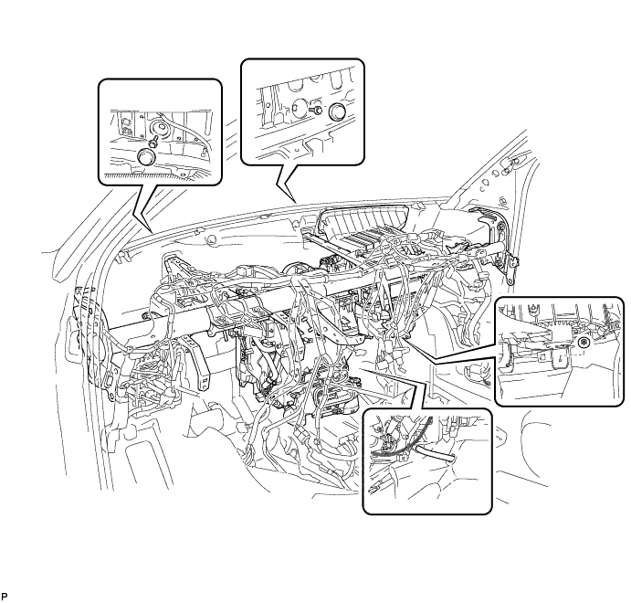
Remove the 2 caps and the 2 bolts from the engine compartment side.
-
Disconnect the cooler drain hose.
-
Remove the nut.
-
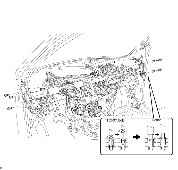
Using a "TORX" socket wrench (T40), remove the 5 "TORX" bolts.
Tech Tips
The "TORX" bolts on the passenger side can be removed with the collars for adjustment.
-
Using a 12 mm hexagon wrench, remove the 2 collars and the instrument panel reinforcement assembly with air conditioning unit.
-
-
REMOVE INSTRUMENT PANEL REINFORCEMENT ASSEMBLY WITH AIR CONDITIONING UNIT (w/ PTC Heater)
-
Disengage each clamp.
-
Remove the 2 bolts and disconnect the 2 earth wires.
-
Disconnect each connector.
-
Remove the 2 nuts and bolt.
-
Disconnect the blower motor connector.
-
Disconnect the 2 quick heater connectors.
-
Remove the 2 caps and the 2 bolts from the engine compartment side.
-
Disconnect the cooler drain hose.
-
Remove the nut.
-
Using a "TORX" socket wrench (T40), remove the 5 "TORX" bolts.
Tech Tips
The "TORX" bolts on the passenger side can be removed with the collars for adjustment.
-
Using a 12 mm hexagon wrench, remove the 2 collars and the instrument panel reinforcement assembly with air conditioning unit.
-
-
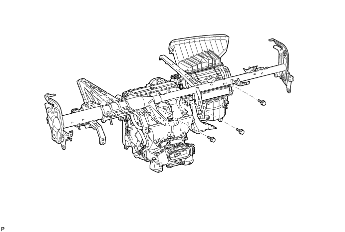
REMOVE AIR CONDITIONING UNIT
-
Remove the 3 bolts and the air conditioning unit from the instrument panel reinforcement assembly.
-
-
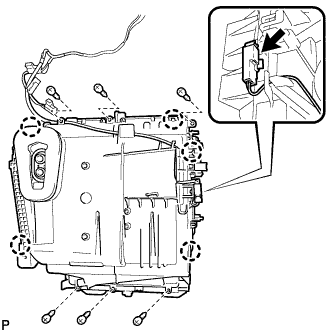
REMOVE BLOWER ASSEMBLY
-
Disconnect the connector.
-
Remove the 2 screws.
-
Disengage the 2 claws and remove the blower assembly.
-
-
REMOVE COOLER EXPANSION VALVE
-
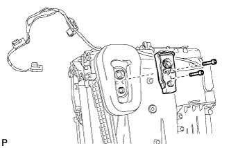
Using a 4 mm hexagon wrench, remove the 2 hexagon bolts and cooler expansion valve.
-
-
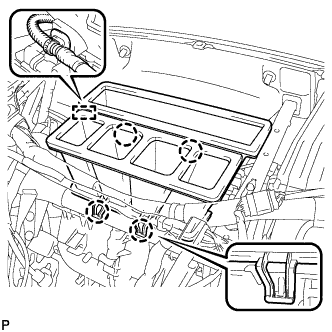
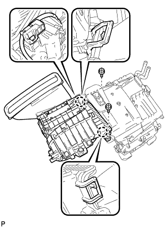
REMOVE NO. 1 COOLER EVAPORATOR SUB-ASSEMBLY
-
Disconnect the connector.
-
Remove the 6 screws.
-
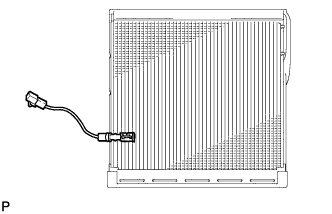
Disengage the 5 claws and remove the plate cover.
-
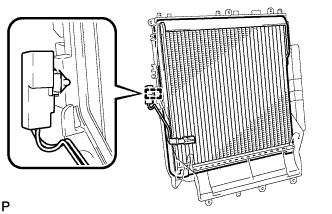
Disengage the clamp and remove the No. 1 cooler evaporator sub-assembly with the No. 1 cooler thermistor.
-
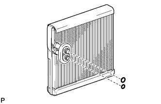
Remove the 2 O-rings from the No. 1 cooler evaporator sub-assembly.
-
-
REMOVE NO. 1 COOLER THERMISTOR
-
Remove the No. 1 cooler thermistor.
-