COMPRESSOR INSTALLATION
-
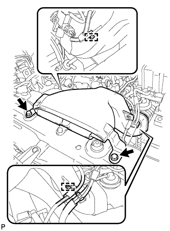
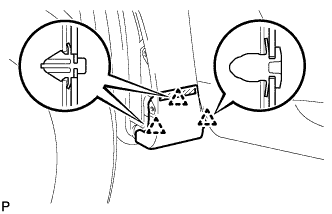
TEMPORARILY TIGHTEN COMPRESSOR AND MAGNETIC CLUTCH
-
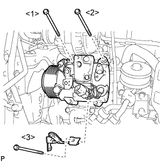
Temporarily install the compressor and magnetic clutch with the bolts.
Tech Tips
Temporarily tighten the bolts in the order shown in the illustration.
-
-
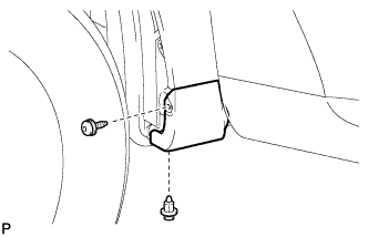
INSTALL COMPRESSOR AND MAGNETIC CLUTCH
-
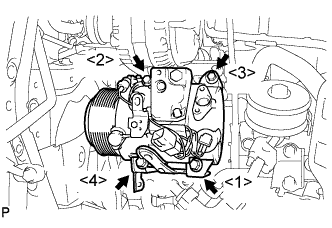
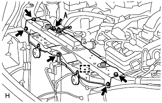
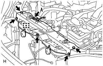
Install the compressor and magnetic clutch with the 4 bolts.
- Torque:
- 25 N*m { 255 kgf*cm, 18 ft.*lbf }
Note
Tighten the bolts in the order shown in the illustration to install the compressor and magnetic clutch.
-
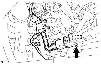
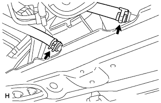
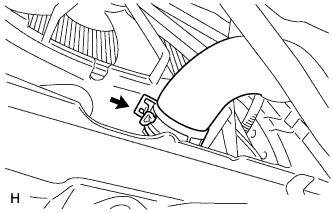
Engage each clamp.
-
Connect the connector.
-
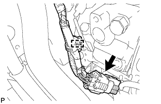
Engage the clamp.
-
Connect the connector.
-
-
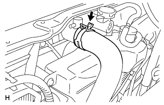
CONNECT SUCTION HOSE SUB-ASSEMBLY
-
Remove the attached vinyl tape from the hose.
-
Apply sufficient compressor oil to a new O-ring and the fitting surface of the compressor and magnetic clutch.
Compressor oil ND-OIL 8 or equivalent -
Install the O-ring onto the suction hose sub-assembly.
-
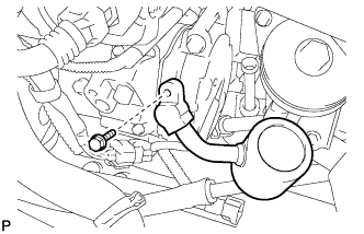
Install the suction hose sub-assembly onto the compressor and magnetic clutch with the bolt.
- Torque:
- 9.8 N*m { 100 kgf*cm, 87 in.*lbf }
-
-
CONNECT DISCHARGE HOSE SUB-ASSEMBLY
-
Remove the attached vinyl tape from the hose.
-
Apply sufficient compressor oil to a new O-ring and the fitting surface of the compressor and magnetic clutch.
Compressor oil ND-OIL 8 or equivalent -
Install the O-ring onto the discharge hose sub-assembly.
-
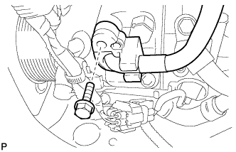
Install the discharge hose sub-assembly onto the compressor and magnetic clutch with the bolt.
- Torque:
- 9.8 N*m { 100 kgf*cm, 87 in.*lbf }
-
-
INSTALL RADIATOR ASSEMBLY AND FAN ASSEMBLY WITH MOTOR
-
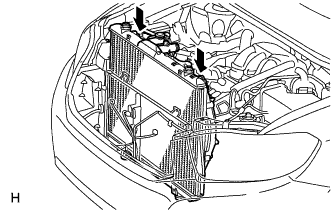
Install the radiator assembly and fan assembly with motor.
-
-
INSTALL COOLER CONDENSER ASSEMBLY
-
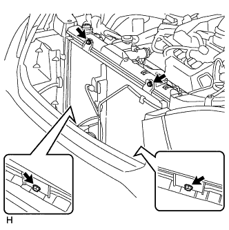
Install the cooler condenser assembly with the 4 bolts.
- Torque:
- 6.0 N*m { 61 kgf*cm, 53 in.*lbf }
-
-
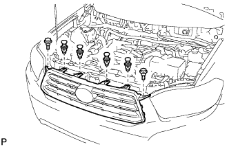
INSTALL UPPER RADIATOR SUPPORT SUB-ASSEMBLY (for LHD)
-
Install the upper radiator support sub-assembly with the 6 bolts and attach the hood lock control cable clamp to the radiator support.
- Torque:
- Bolt A
- 9.8 N*m { 100 kgf*cm, 87 in.*lbf }
-
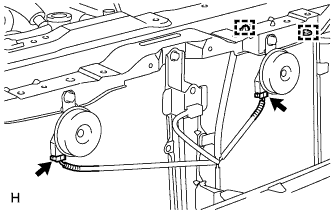
Connect the low pitched horn and high pitched horn connectors.
-
-
INSTALL UPPER RADIATOR SUPPORT SUB-ASSEMBLY (for RHD)
-
Install the upper radiator support sub-assembly with the 6 bolts and attach the hood lock control cable clamp to the radiator support.
- Torque:
- Bolt A
- 9.8 N*m { 100 kgf*cm, 87 in.*lbf }
-
Connect the low pitched horn and high pitched horn connectors.
-
-
INSTALL HOOD LOCK ASSEMBLY (w/o Engine Hood Courtesy Switch)
-
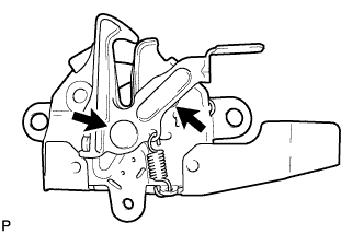
Apply MP grease to the sliding areas of the lock.
-
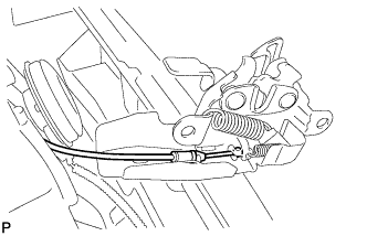
Connect the hood lock control cable.
-
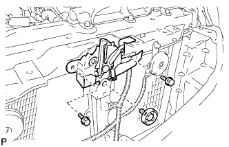
Install the hood lock assembly with the 3 bolts.
- Torque:
- 8.0 N*m { 82 kgf*cm, 71 in.*lbf }
-
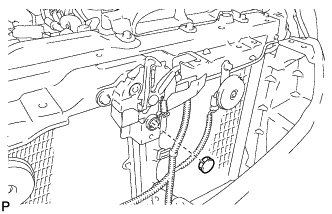
Install the hood lock nut cap.
-
-
INSTALL HOOD LOCK ASSEMBLY (w/ Engine Hood Courtesy Switch)
-
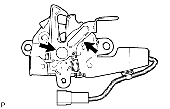
Apply MP grease to the sliding areas of the lock.
-
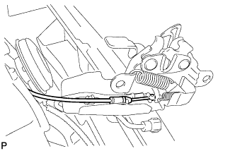
Connect the hood lock control cable.
-
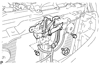
Install the hood lock assembly with the 3 bolts.
- Torque:
- 8.0 N*m { 82 kgf*cm, 71 in.*lbf }
-
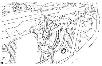
Install the hood lock nut cap.
-
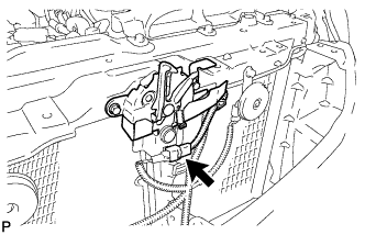
Connect the connector.
-
-
INSTALL RADIATOR GRILLE
-
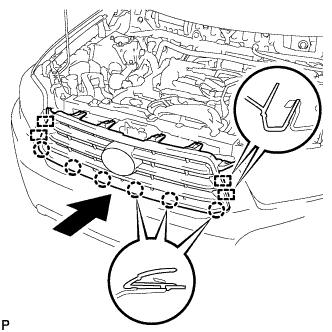
Engage the 4 guides and 6 claws, and install the radiator grille.
-
Install the 4 clips and 2 bolts.
-
-
CONNECT COOLING FAN ECU CONNECTOR
-
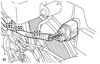
Connect the cooling fan ECU connector and attach the wire harness clamps to the fan shroud RH side.
-
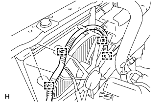
Attach the wire harness clamps to the fan shroud LH side.
-
-
CONNECT OIL COOLER HOSE
-
Connect the oil cooler hoses to the radiator.
-
-
CONNECT NO. 2 RADIATOR HOSE
-
Connect the No. 2 radiator hose to the radiator.
-
-
CONNECT NO. 1 RADIATOR HOSE
-
Connect the No. 1 radiator hose to the radiator.
-
-
INSTALL NO. 1 AIR CLEANER INLET
-
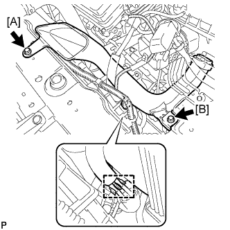
Install the No. 1 air cleaner inlet with the 2 bolts.
- Torque:
- 7.0 N*m { 71 kgf*cm, 62 in.*lbf, [A] }
- Torque:
- 5.0 N*m { 51 kgf*cm, 44 in.*lbf, [B] }
-
Connect the 2 vacuum hoses.
-
-
INSTALL NO. 2 AIR CLEANER INLET
-
Install the No. 2 air cleaner inlet with the 2 bolts.
- Torque:
- 7.0 N*m { 71 kgf*cm, 62 in.*lbf }
-
Connect the 2 vacuum hoses and harness clamps.
-
-
INSTALL BATTERY
Note
When reconnected the cable, some systems need to be initialized. Click here.
-
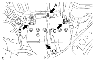
Install the battery tray and battery.
-
Install the battery clamp with the bolt and nut.
- Torque:
- Bolt
- 5.4 N*m { 55 kgf*cm, 47 in.*lbf }
- Nut A
- 5.4 N*m { 55 kgf*cm, 47 in.*lbf }
-
Connect the positive battery terminal, and tighten the nut.
- Torque:
- Nut B
- 6.4 N*m { 64 kgf*cm, 57 in.*lbf }
-
Connect the negative battery terminal, and tighten the nut.
- Torque:
- Nut C
- 6.4 N*m { 64 kgf*cm, 57 in.*lbf }
-
-
INSTALL COOL AIR INTAKE DUCT SEAL
-
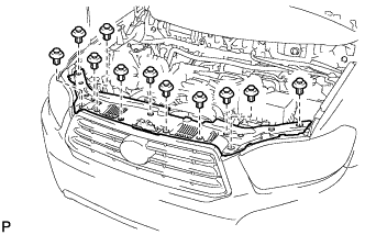
Install the cool air intake duct seal with the 11 clips.
-
-
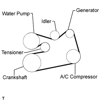
INSTALL V-RIBBED BELT
-
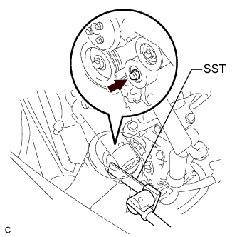
Install the V-ribbed belt.
-
Using SST, turn the V-ribbed belt tensioner assembly counterclockwise and remove the bar.
- SST
- 09961-00950
-
If it is difficult to install the V-ribbed belt, perform the following procedure:
-
Put the V-ribbed belt on every pulley except the tensioner pulley as shown in the illustration.
-
Release the V-ribbed belt tension by turning the V-ribbed belt tensioner assembly counterclockwise, and put the V-ribbed belt on the V-ribbed belt tensioner assembly pulley.
Note
-
Put the backside of the V-ribbed belt on the V-ribbed belt tensioner assembly pulley and No. 2 idler pulley sub-assembly.
-
Check that the V-ribbed belt is properly set to each pulley.
-
-
After installing the V-ribbed belt, check that it fits properly in the ribbed grooves. Confirm that the V-ribbed belt has not slipped out of the grooves on the bottom of the crankshaft pulley by hand.
-
-
-
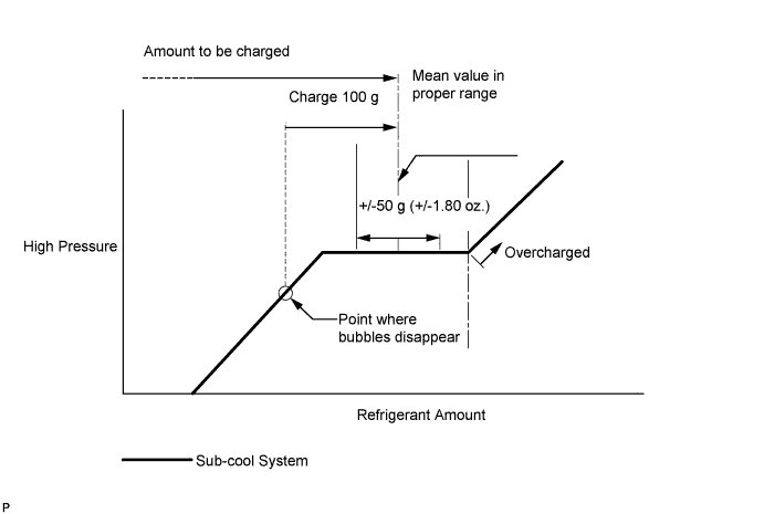
CHARGE WITH REFRIGERANT
-
Perform vacuum purging using a vacuum pump.
-
Charge with refrigerant HFC-134a (R134a).
Standard (w/o Rear Air Conditioning System) 550 to 650 g (19.4 to 22.9 oz.) Standard (w/ Rear Air Conditioning System) 720 to 820 g (25.4 to 28.9 oz.) - SST
- 09985-20010 ( 09985-02010, 09985-02050, 09985-02060, 09985-02070, 09985-02080, 09985-02090, 09985-02110, 09985-02130, 09985-02140, 09985-02150 )
Note
-
Do not turn the A/C on before charging with refrigerant. Doing so will cause the cooler compressor to work without refrigerant, resulting in overheating of the cooler compressor.
-
Approximately 100 g (3.53 oz.) of refrigerant may need to be charged after bubbles disappear. The refrigerant amount should be checked by quantity, not with the sight glass.
Tech Tips
Ensure that sufficient refrigerant is available to recharge the system when using a refrigerant recovery unit. Refrigerant recovery units are not always able to recover 100% of the refrigerant from an A/C system.
-
-
ADD ENGINE COOLANT
-
Tighten the radiator drain cock plug by hand.
-
Tighten the 2 cylinder block drain cock plugs.
- Torque:
- 13 N*m { 130 kgf*cm, 9 ft.*lbf, for cylinder block drain cock plugs }
-
Loosen the air drain cock plug from the water inlet housing.
-
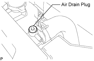
Loosen the air drain plug at the top of the radiator 3 or 4 turns.
-
Add TOYOTA Super Long Life Coolant (SLLC) to the radiator inlet opening until coolant overflows from the engine air drain cock hole. Then tighten the air drain cock plug to the water inlet housing.
- Torque:
- 13 N*m { 130 kgf*cm, 9 ft.*lbf, for air drain cock plug }
-
Continue to add TOYOTA Super Long Life Coolant (SLLC) to the radiator inlet opening until coolant overflows from the radiator air drain hole. Then close the air drain plug at the top of the radiator.
- Torque:
- 1.5 N*m { 15 kgf*cm, 13 in.*lbf, for air drain plug }
Tech Tips
If the coolant level at the radiator inlet opening drops after squeezing the No. 1 and No. 2 radiator hoses, add coolant.
-
Slowly fill the radiator with TOYOTA Super Long Life Coolant (SLLC).
Standard capacity w/o Engine oil cooler Condition Specified Condition w/ Rear Heater 11.0 liters (11.6 US qts, 9.7 Imp. qts) w/o Rear Heater 8.8 liters (9.3 US qts, 7.7 Imp. qts) w/ Engine oil cooler Condition Specified Condition w/ Rear Heater 11.7 liters (12.4 US qts, 10.3 Imp. qts) w/o Rear Heater 9.5 liters (10.1 US qts, 8.4 Imp. qts) Tech Tips
-
TOYOTA vehicles are filled with TOYOTA SLLC at the factory. In order to avoid damage to the engine cooling system and other technical problems, only use TOYOTA SLLC or similar high quality ethylene glycol based non-silicate, non-amine, non-nitrite, non-borate coolant with long-life hybrid organic acid technology (coolant with long-life hybrid organic acid technology consists of a combination of low phosphates and organic acids).
-
Contact your TOYOTA dealer for further details.
Note
Never use water as a substitute for engine coolant.
-
-
Slowly pour coolant into the radiator reservoir tank until it reaches the FULL line.
-
Squeeze the No. 1 and No. 2 radiator hoses several times by hand, and then check the level of the coolant.
If the coolant level is low, add coolant.
-
Bleed air from the cooling system.
-
Warm up the engine until the thermostat opens. While the thermostat is open, circulate the coolant for several minutes.
Tech Tips
The thermostat open timing can be confirmed by squeezing the inlet radiator hose by hand, and checking when the engine coolant starts to flow inside the hose.
-
Maintain the engine speed at 2500 to 3000 rpm.
-
Squeeze the inlet and outlet radiator hoses several times by hand to bleed air.
CAUTION:
When squeezing the radiator hoses:
-
Wear protective gloves.
-
Be careful as the radiator hoses are hot.
-
Keep your hands away from the radiator fan.
Note
-
Make sure that the radiator reservoir still has some coolant in it.
-
If the coolant temperature gauge indicates an excessive temperature, turn off the engine and let it cool.
-
If there is not enough coolant, the engine may overheat or be seriously damaged.
-
If the radiator reservoir does not have enough coolant, perform the following: 1) stop the engine, 2) wait until the coolant has cooled down, and 3) add coolant until the reservoir is filled to the FULL line.
-
-
-
Stop the engine and wait until the engine coolant cools down.
-
Add engine coolant to the FULL line on the radiator reservoir.
-
-
INSTALL FRONT FENDER APRON SEAL RH
-
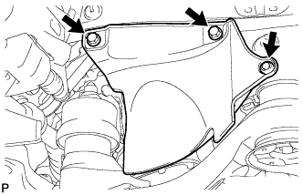
Install the front fender apron seal RH with the 2 bolts and clip.
-
-
INSTALL FRONT FENDER LINER RH
-
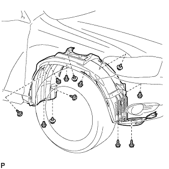
Install the front fender liner RH with the 5 clips and 7 screws.
-
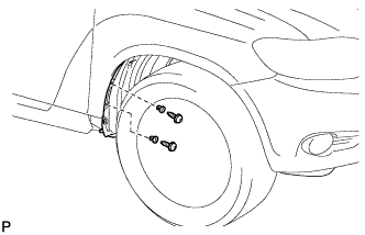
Install 2 new grommets.
-
Using a 4 mm hexagon wrench, install the 2 screws.
-
Install the screw and pin hold clip.
- Torque:
- 3.0 N*m { 31 kgf*cm, 27 in.*lbf }
-
-
INSTALL FRONT FENDER MOULDING SUB-ASSEMBLY RH
-
Clean the vehicle body surface.
-
Using a heat light, heat the vehicle body surface.
-
Remove the front fender side protector from the vehicle body.
-
Wipe off any tape adhesive residue with cleaner.
-
-
Clean the front fender moulding sub-assembly. (If reusing the front fender moulding sub-assembly)
-
Using a heat light, heat the front fender moulding sub-assembly.
-
Remove the front fender side protector from the front fender moulding sub-assembly.
-
Wipe off any tape adhesive residue with cleaner.
-
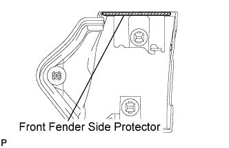
Install a new front fender side protector to the the front fender moulding sub-assembly.
-
-
Install 2 new No. 4 clips on the front fender moulding sub-assembly.
-
Install a new pad on the front fender moulding sub-assembly.
-
Install the front fender moulding sub-assembly.
-
Using a heat light, heat the vehicle body and the front fender moulding sub-assembly.
-
Remove the release paper from the front fender moulding sub-assembly.
Tech Tips
After removing the release paper, keep the exposed adhesive free from foreign matter.
-
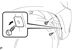
Engage the 3 clips and install the front fender moulding sub-assembly.
-
-
Using a 4 mm hexagon wrench, install the screw.
-
Install the clip.
-
-
INSTALL FRONT WHEEL RH
-
WARM UP ENGINE
-
Keep the A/C switch on for at least 2 minutes to warm up the compressor.
Note
Be sure to warm up the compressor when turning the A/C on after removing and installing the cooler refrigerant lines (including the compressor), to prevent damage to the compressor.
-
-
INSPECT FOR REFRIGERANT LEAK
-
After recharging with refrigerant gas, inspect for refrigerant leak using a halogen leak detector.
-
Carry out the test under the following conditions:
-
Make sure that the ignition switch is off.
-
Secure good ventilation (the gas leak detector may react to volatile gases which are not refrigerant, such as evaporated gasoline and exhaust gas).
-
Repeat the test 2 or 3 times.
-
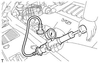
Make sure that there is some refrigerant remaining in the refrigeration system.
When the compressor is off: approx. 392 to 588 kPa (4 to 6 kgf/cm2, 57 to 85 psi)
-
-
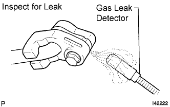
Using a gas leak detector, inspect for refrigerant leak from the refrigerant lines.
-
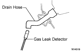
Bring the gas leak detector close to the drain hose with the detector's power off, and then turn the detector on.
Tech Tips
-
After the blower motor has stopped, let the cooling unit stand for more than 15 minutes.
-
Bring the gas leak detector sensor under the drain hose.
-
When bringing the gas leak detector close to the drain hose, make sure that the gas leak detector does not react to volatile gases.
If it is not possible to avoid interference from volatile gases, the vehicle should be lifted up to allow testing.
-
-
If a gas leak is not detected from the drain hose, remove the blower motor from the cooling unit. Insert the gas leak detector into the unit and perform the test.
-
Disconnect the pressure switch connector and leave it for approximately 20 minutes. Bring the gas leak detector close to the pressure switch and perform the test.
-
-
INSPECT FOR COOLANT LEAK
CAUTION:
Do not remove the radiator cap while the engine and radiator are still hot. Pressurized, hot engine coolant and steam may be released and cause serious burns.
Note
Before performing each inspection, turn the A/C switch off.
-
Fill the radiator with coolant and attach a radiator cap tester.
-
Warm up the engine.
-
Using the radiator cap tester, increase the pressure inside the radiator to 118 kPa (1.2 kgf/cm2, 17 psi), and check that the pressure does not drop.
If the pressure drops, check the hoses, radiator and water pump for leaks. If no external leaks are found, check the heater core, cylinder block and cylinder head.
-
-
INSPECT AUTOMATIC TRANSAXLE FLUID
for U151E: Click here
for U151F: Click here
-
INSPECT FOR OIL LEAK
-
INSTALL NO. 1 ENGINE UNDER COVER
-
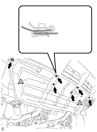
Install the No. 1 engine under cover with the 6 bolts and 2 clips.
-
-
INSTALL ENGINE UNDER COVER ASSEMBLY
-

Install the engine under cover assembly with the 2 bolts, 2 screws and 5 clips.
-

Install the engine under cover assembly RR with the 2 bolts.
-
-
INSTALL V-BANK COVER SUB-ASSEMBLY
-
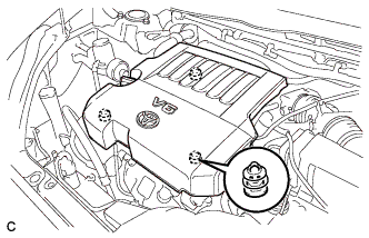
Fit the 3 retainers and install the V-bank cover.
-