- Click here
INSTALL MAGNETIC CLUTCH ASSEMBLY
-
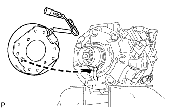
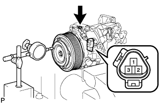
Install the magnetic clutch stator while aligning the protrusion on the stator with the notch on the compressor assembly as shown in the illustration.
-
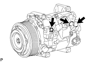
Engage the clamp.
-
Install the bracket with the screw.
-
Connect the connector.
-
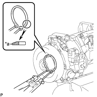
Using a snap ring expander, install a new snap ring with the chamfered side facing up.
Table 1. Text in Illustration *a Inside Note:Take care not to damage the seal cover of the bearing when installing the snap ring.
-
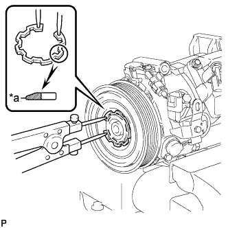
Using a snap ring expander, install the magnetic clutch rotor and a new snap ring with the chamfered side facing up.
Table 2. Text in Illustration *a Inside Note:
-
Do not expand the snap ring by more than 35.5 mm (1.39 in.) when installing it.
-
Do not damage the seal cover of the bearing when installing the snap ring.
-
-
Install the magnetic clutch washer and magnetic clutch hub.
Note:Do not change the combination of the magnetic clutch washers used before disassembly.
-
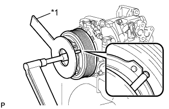
Using SST, hold the magnetic clutch hub and install the bolt.
Table 3. Text in Illustration *1 SST 09985-00270 18 N*m 184 kgf*cm 13 ft.*lbf Note:Make sure that there is no foreign matter or oil on the compressor shaft, bolt, and clutch hub.
-
- Click here
INSPECT MAGNETIC CLUTCH CLEARANCE
-
Set the dial indicator to the magnetic clutch hub.
-
Connect the battery positive (+) lead to terminal 1 of the magnetic clutch connector, and the negative (-) lead to the ground wire. Turn the magnetic clutch on and off and measure the clearance.
Standard clearance 0.26 to 0.60 mm (0.010 to 0.024 in.) If the measured value is not within the standard range, remove the magnetic clutch hub and adjust it with magnetic clutch washers.
Note:Adjustment should be performed with 3 or less magnetic clutch washers.
-
Remove the compressor and magnetic clutch from the vise.
-
- Click here
ADJUST COMPRESSOR OIL LEVEL
-
When replacing the compressor and magnetic clutch with a new one, gradually discharge the refrigerant gas from the service valve, and drain the following amount of oil from the new compressor and magnetic clutch before installation.
Standard (w/o Rear Air Conditioning System) (Oil capacity inside the new compressor and magnetic clutch: 100 + 15 cc (3.38 + 0.51 fl.oz.) ) - (Remaining oil amount in the removed compressor and magnetic clutch) = (Oil amount to be removed from the new compressor when replacing) Standard (w/ Rear Air Conditioning System) (Oil capacity inside the new compressor and magnetic clutch: 140 + 15 cc (4.73 + 0.51 fl.oz.) ) - (Remaining oil amount in the removed compressor and magnetic clutch) = (Oil amount to be removed from the new compressor when replacing) Note:
-
When checking the compressor oil level, observe the precautions on the cooler removal/installation.
-
If a new compressor and magnetic clutch are installed without removing some oil, due to the oil remaining in the pipes of the vehicle, the oil amount will be too large. This prevents heat exchange in the refrigerant cycle and causes refrigerant failure.
-
If the volume of oil remaining in the removed compressor and magnetic clutch is too small, check for oil leakage.
-
Be sure to use ND-OIL 8 or equivalent for compressor oil.
-
-