COMPRESSOR REMOVAL
-
RECOVER REFRIGERANT FROM REFRIGERATION SYSTEM
-
Start the engine.
-
Turn the A/C switch on.
-
Operate the cooler compressor at an engine speed of approximately 1000 rpm for 5 to 6 minutes to circulate the refrigerant. This causes most of the compressor oil from the various components of the A/C system to collect in the A/C compressor.
-
Stop the engine.
-
Recover the refrigerant from the A/C system using a refrigerant recovery unit.
-
-
REMOVE FRONT WHEEL RH
-
REMOVE ENGINE UNDER COVER ASSEMBLY
-

Remove the 2 bolts and engine under cover assembly RR.
-

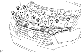
Remove the 2 bolts, 2 screws, 5 clips and engine under cover assembly.
-
-
REMOVE NO. 1 ENGINE UNDER COVER
-
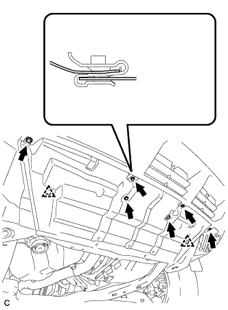
Remove the 6 bolts, 2 clips and No. 1 engine under cover.
-
-
REMOVE FRONT FENDER MOULDING SUB-ASSEMBLY RH
-
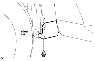
Remove the clip.
-
Using a 4 mm hexagon wrench, remove the screw.
-
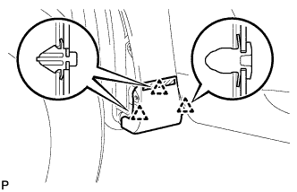
Peel off the front fender side protector and disengage the 3 clips, and then remove the front fender moulding sub-assembly.
-
Remove the pad from the front fender moulding sub-assembly.
-
Remove the 2 No. 4 clips from the front fender moulding sub-assembly.
-
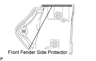
Remove the front fender side protector from the front fender moulding sub-assembly.
-
-
REMOVE FRONT FENDER LINER RH
-
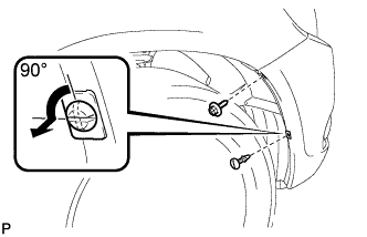
Remove the screw.
-
Using a screwdriver, turn the pin 90 degrees and remove the pin hold clip.
-
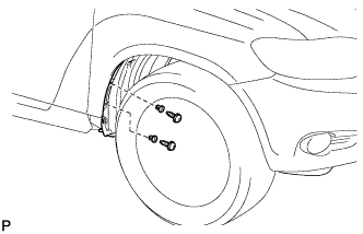
Using a 4 mm hexagon wrench, remove the 2 screws.
-
Remove the 2 grommets.
Tech Tips
The grommets need to be replaced with new ones because they will break when they are removed.
-
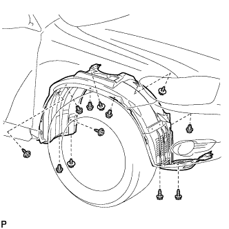
Remove the 5 clips, 7 screws and front fender liner RH.
-
-
REMOVE FRONT FENDER APRON SEAL RH
-
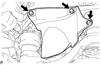
Remove the 2 bolts, clip and front fender apron seal RH.
-
-
REMOVE V-RIBBED BELT
-
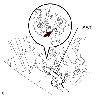
Using SST, release the V-ribbed belt tension by turning the V-ribbed belt tensioner assembly counterclockwise, and remove the V-ribbed belt from the V-ribbed belt tensioner assembly.
- SST
- 09961-00950
-
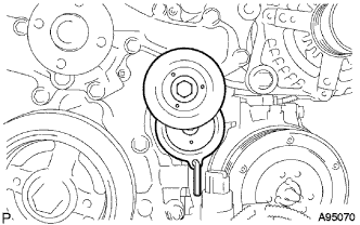
While turning the V-ribbed belt tensioner assembly counterclockwise, align with its holes, and then insert the 5 mm bi-hexagon wrench into the holes to fix the V-ribbed belt tensioner assembly.
-
-
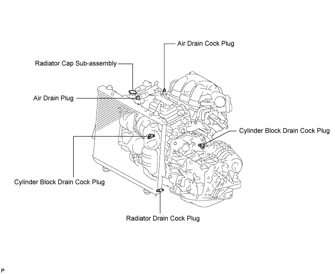
DRAIN ENGINE COOLANT
-
Loosen the radiator drain cock plug.
Tech Tips
Collect the coolant in a container and dispose of it according to the regulations in your area.
-
Remove the radiator cap sub-assembly from the radiator assembly.
Note
Do not remove the radiator cap sub-assembly while the engine and radiator are still hot. Pressurized, hot engine coolant and steam may be released and cause serious burns.
-
Loosen the 2 cylinder block drain cock plugs.
-
-
REMOVE V-BANK COVER SUB-ASSEMBLY
-
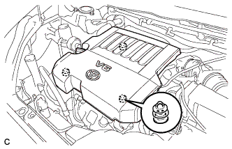
Hold the front of the V-bank cover sub-assembly and raise it to disengage the 2 clips on the front of the V-bank cover sub-assembly. Continue rising the V-bank cover sub-assembly to disengage the clip on the rear of the V-bank cover sub-assembly and remove the V-bank cover sub-assembly.
Note
Attempting to disengage both front and rear clips at the same time may cause the V-bank cover sub-assembly to break.
-
-
REMOVE COOL AIR INTAKE DUCT SEAL
-
Remove the 11 clips and cool air intake duct seal.
-
-
REMOVE BATTERY
CAUTION:
Wait at least 90 seconds after disconnecting the cable from the negative (-) battery terminal to prevent airbag and seat belt pretensioner activation.
Note
When disconnecting the cable, some systems need to be initialized after the cable is reconnected Click here.
-
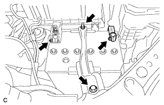
Loosen the nut, and disconnect the negative battery terminal.
-
Loosen the nut, and disconnect the positive battery terminal.
-
Loosen the nut, and remove the bolt and battery clamp.
-
Remove the battery and battery tray.
-
-
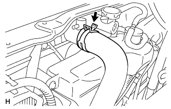
REMOVE NO. 2 AIR CLEANER INLET
-
Disconnect the 2 vacuum switching valve clamps.
-
Disconnect the 2 vacuum hoses.
-
Remove the 2 bolts and No. 2 air cleaner inlet.
-
-
REMOVE NO. 1 AIR CLEANER INLET
-
Disconnect the 2 vacuum hoses, and remove the 2 bolts and No. 1 air cleaner inlet.
-
-
DISCONNECT NO. 1 RADIATOR HOSE
-
Disconnect the No. 1 radiator hose from the radiator.
-
-
DISCONNECT NO. 2 RADIATOR HOSE
-
Disconnect the No. 2 radiator hose from the radiator.
-
-
DISCONNECT OIL COOLER HOSE
-
Disconnect the oil cooler hoses from the radiator.
-
-
DISCONNECT COOLING FAN ECU CONNECTOR
-
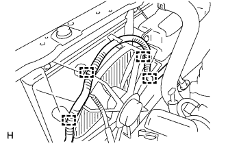
Detach the wire harness clamps from the fan shroud LH side.
-
Detach the wire harness clamps from the fan shroud RH side and disconnect the cooling fan ECU connector.
-
-
REMOVE RADIATOR GRILLE
-
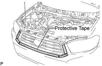
Put protective tape around the radiator grille.
-
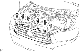
Remove the 2 bolts and 4 clips.
-
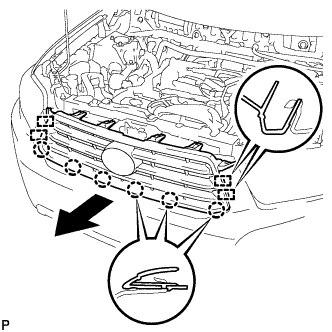
Disengage the 6 claws and 4 guides, and remove the radiator grille.
-
-
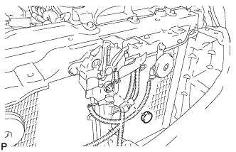
REMOVE HOOD LOCK ASSEMBLY (w/o Engine Hood Courtesy Switch)
-
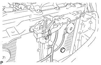
Remove the hood lock nut cap.
-
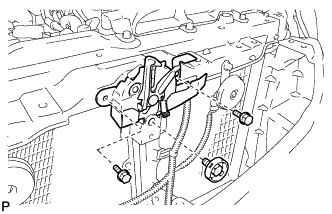
Remove the 3 bolts.
-
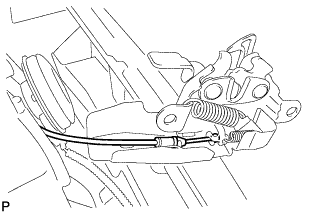
Disconnect the hood lock control cable and remove the hood lock assembly.
-
-
REMOVE HOOD LOCK ASSEMBLY (w/ Engine Hood Courtesy Switch)
-
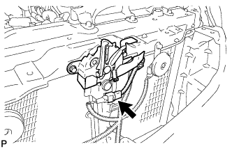
Disconnect the connector.
-
Remove the hood lock nut cap.
-
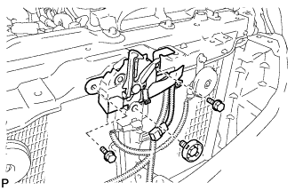
Remove the 3 bolts.
-
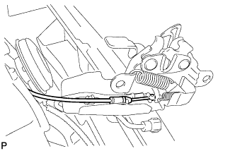
Disconnect the hood lock control cable and remove the hood lock assembly.
-
-
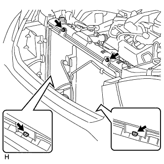
REMOVE UPPER RADIATOR SUPPORT SUB-ASSEMBLY (for LHD)
-
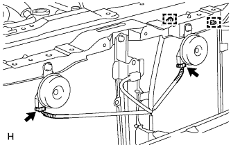
Disconnect the low pitched horn and high pitched horn connectors.
-
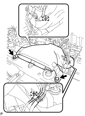
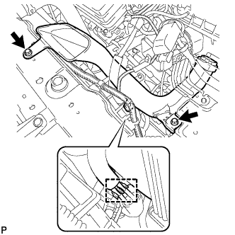
Detach the hood lock control cable clamp and remove the 6 bolts and upper radiator support sub-assembly.
-
-
REMOVE UPPER RADIATOR SUPPORT SUB-ASSEMBLY (for RHD)
-
Disconnect the low pitched horn and high pitched horn connectors.
-
Detach the hood lock control cable clamp and remove the 6 bolts and upper radiator support sub-assembly.
-
-
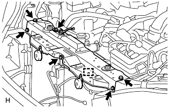
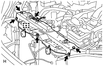
SEPARATE COOLER CONDENSER ASSEMBLY
-
Remove the 4 bolts and move the cooler condenser assembly to remove the radiator assembly and fan assembly with motor.
-
-
REMOVE RADIATOR ASSEMBLY AND FAN ASSEMBLY WITH MOTOR
-
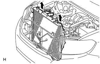
Remove the radiator assembly and fan assembly with motor.
-
-
DISCONNECT DISCHARGE HOSE SUB-ASSEMBLY
-
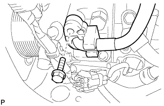
Remove the bolt and disconnect the discharge hose sub-assembly from the compressor and magnetic clutch.
-
Remove the O-ring from the discharge hose sub-assembly.
Note
Seal the openings of the disconnected parts using vinyl tape to prevent entry of moisture and foreign matter.
-
-
DISCONNECT SUCTION HOSE SUB-ASSEMBLY
-
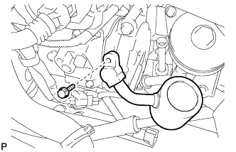
Remove the bolt and disconnect the suction hose sub-assembly from the compressor and magnetic clutch.
-
Remove the O-ring from the suction hose sub-assembly.
Note
Seal the openings of the disconnected parts using vinyl tape to prevent entry of moisture and foreign matter.
-
-
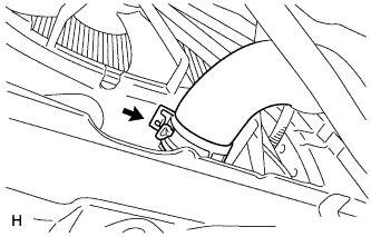
REMOVE COMPRESSOR AND MAGNETIC CLUTCH
-
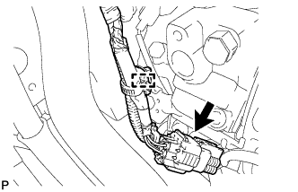
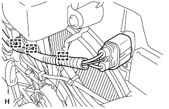
Disengage the clamp.
-
Disconnect the connector.
-
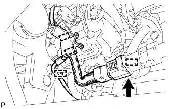
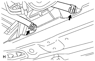
Disengage each clamp.
-
Disconnect the connector.
-
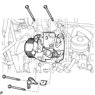
Remove the 4 bolts and the compressor and magnetic clutch.
-