AIR OUTLET CONTROL SERVO MOTOR (for Rear) REMOVAL
Tech Tips
Adjust the air outlet mode setting to FOOT.
-
RECOVER REFRIGERANT FROM REFRIGERATION SYSTEM
-
Start the engine.
-
Turn the A/C switch on.
-
Operate the cooler compressor at an engine speed of approximately 1000 rpm for 5 to 6 minutes to circulate the refrigerant. This causes most of the compressor oil from the various components of the A/C system to collect in the A/C compressor.
-
Stop the engine.
-
Recover the refrigerant from the A/C system using a refrigerant recovery unit.
-
-
DISCONNECT REAR HEATER OUTLET WATER HOSE
-
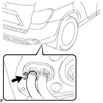
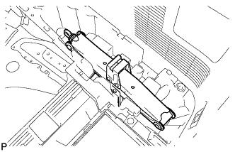
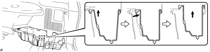
Using pliers, grip the claws of the clip and slide the clip to disconnect the rear heater outlet water hose.
Note
-
Do not apply excessive force to the rear heater outlet water hose.
-
Prepare a drain pan or cloth in case the coolant leaks.
-
-
-
DISCONNECT REAR HEATER INLET WATER HOSE
-
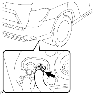
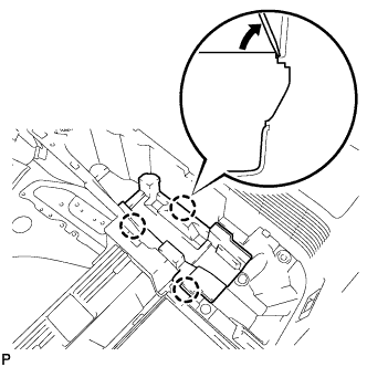
Using pliers, grip the claws of the clip and slide the clip to disconnect the rear heater inlet water hose.
Note
-
Do not apply excessive force to the rear heater inlet water hose.
-
Prepare a drain pan or cloth in case the coolant leaks.
-
-
-
DISCONNECT COOLER REFRIGERANT LIQUID PIPE C
-
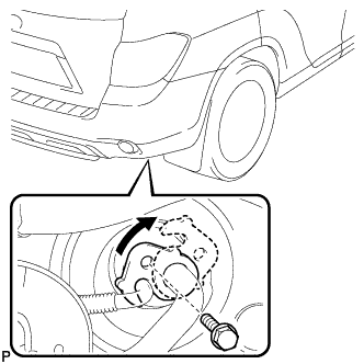
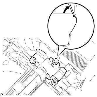
Remove the bolt, and slide the hook connector.
-
Disconnect the cooler refrigerant liquid pipe C.
-
Remove the O-ring from the cooler refrigerant liquid pipe C.
Note
Seal the openings of the disconnected parts using vinyl tape to prevent entry of moisture and foreign matter.
-
-
DISCONNECT COOLER REFRIGERANT SUCTION HOSE
-
Disconnect the rear cooler refrigerant suction hose.
-
Remove the O-ring from the rear cooler refrigerant suction hose.
Note
Seal the openings of the disconnected parts using vinyl tape to prevent entry of moisture and foreign matter.
-
-
REMOVE REAR DOOR SCUFF PLATE RH
Tech Tips
Use the same procedure for the RH side and the LH side.
-
REMOVE REAR DOOR OPENING TRIM WEATHERSTRIP RH
Tech Tips
Use the same procedure for the RH side and the LH side.
-
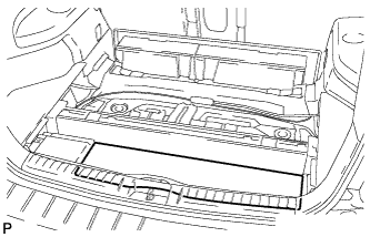
REMOVE DECK BOARD ASSEMBLY
-
Remove the deck board assembly.
-
-
REMOVE NO. 3 DECK BOARD SUB-ASSEMBLY
-
Disengage the 2 guides and remove the No. 3 deck board sub-assembly.
-
-
REMOVE NO. 2 DECK BOARD SUB-ASSEMBLY
-
Disengage the 2 guides and remove the No. 2 deck board sub-assembly.
-
-
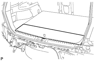
REMOVE TONNEAU COVER ASSEMBLY (w/ Tonneau Cover)
-
Remove the tonneau cover assembly.
-
-
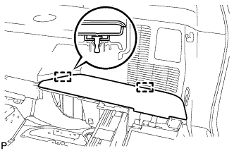
REMOVE REAR SEAT SIDE COVER LH
-
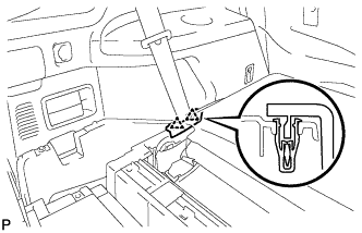
Disengage the 2 clips and remove the rear seat side cover LH.
-
-
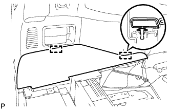
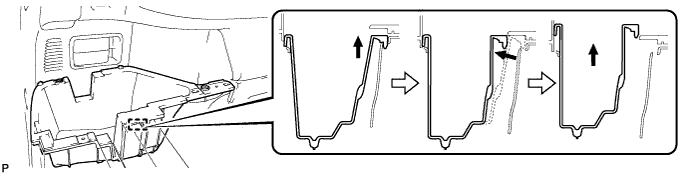
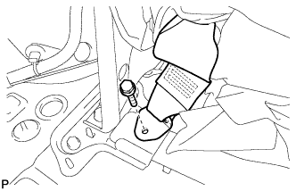
REMOVE DECK SIDE TRIM BOX LH
-
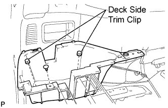
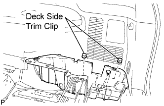
Remove the 2 deck side trim clips and clip.
-
Remove the deck side trim box LH as shown in the illustration.
-
-
REMOVE REAR SEAT SIDE COVER RH
-
Disengage the 2 clips and remove the rear seat side cover RH.
-
-
REMOVE JACK CARRIER SUPPORT
-
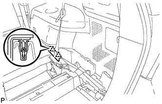
REMOVE JACK CARRIER CUSHION (for LHD)
-
Remove the jack carrier cushion.
-
-
REMOVE JACK CARRIER CUSHION (for RHD)
-

Remove the jack carrier cushion.
-
-
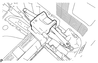
REMOVE JACK ASSEMBLY (for LHD)
-
Remove the jack assembly.
-
-
REMOVE JACK ASSEMBLY (for RHD)
-
Remove the jack assembly.
-
-
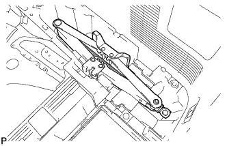
REMOVE JACK CARRIER ASSEMBLY (for LHD)
-
Using a screwdriver, disengage the 3 claws and remove the jack carrier assembly.
-
-
REMOVE JACK CARRIER ASSEMBLY (for RHD)
-
Using a screwdriver, disengage the 3 claws and remove the jack carrier assembly.
-
-
REMOVE DECK SIDE TRIM BOX RH
-
Remove the 2 deck side trim clips and clip.
-
Remove the deck side trim box RH as shown in the illustration.
-
-
REMOVE REAR MAT
-
Remove the rear mat.
-
-
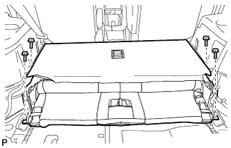
REMOVE DECK FLOOR BOARD ASSEMBLY
-
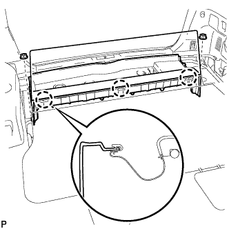
Disengage the 3 claws.
-
Remove the 2 nuts and the deck floor board assembly.
-
-
REMOVE REAR NO. 2 SEAT INNER BELT ASSEMBLY
-
Remove the bolt and rear No. 2 seat inner belt assembly.
Tech Tips
Use the same procedure for the RH side and LH side.
-
-
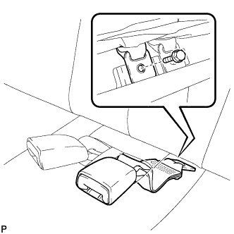
DISCONNECT REAR SEAT LAP TYPE BELT ASSEMBLY LH
-
Remove the bolt and disconnect the rear seat lap type belt assembly LH.
-
-
DISCONNECT REAR SEAT LAP TYPE BELT ASSEMBLY RH
Tech Tips
Use the same procedure for the RH side and the LH side.
-
REMOVE REAR NO. 2 SEAT ASSEMBLY
-
Remove the 4 bolts and the rear No. 2 seat assembly.
-
-
REMOVE REAR FLOOR FINISH PLATE
-
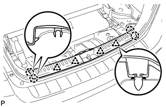
Disengage the 4 clips and the 4 claws, and remove the rear floor finish plate.
-
-
REMOVE REAR SEAT SIDE GARNISH CAP
-
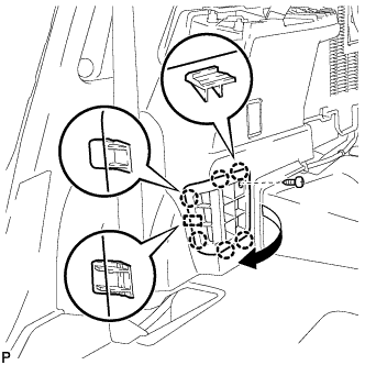
Remove the screw.
-
Disengage the 6 claws and the guide, and remove the rear seat side garnish cap.
-
-
REMOVE DECK SIDE TRIM COVER NO.1
Tech Tips
Use the same procedure for the RH side and the LH side.
-
REMOVE DECK SIDE TRIM RH
Tech Tips
Use the same procedure for the RH side and the LH side.
-
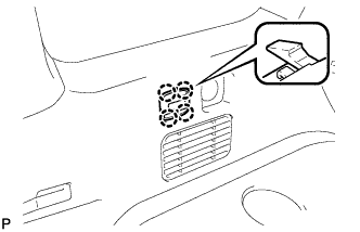
REMOVE SIDE TRIM COVER RH (for Manual Air Conditioning System)
-
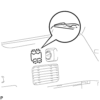
Disengage the 4 claws and remove the side trim cover RH.
-
-
REMOVE REAR ROOM TEMPERATURE SENSOR (for Automatic Air Conditioning System)
-
Disengage the 4 claws and remove the rear room temperature sensor.
-
Disconnect the connector.
-
-
REMOVE REAR COMBINATION LIGHT SERVICE COVER RH
-
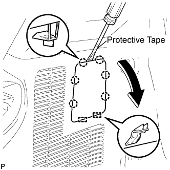
Using a screwdriver, disengage the 6 claws and the 2 guides, and remove the rear combination light service cover RH.
Tech Tips
Tape the screwdriver tip before use.
-
-
REMOVE ROPE HOOK ASSEMBLY (for RH Side)
Tech Tips
Use the same procedure for the RH side and the LH side.
-
REMOVE NO. 1 LUGGAGE COMPARTMENT TRIM HOOK
Tech Tips
Use the same procedure for the No. 1 luggage compartment trim hook and the No. 2 deck side trim hook.
-
REMOVE FRONT DECK SIDE TRIM COVER RH
Tech Tips
Use the same procedure for the RH side and the LH side.
-
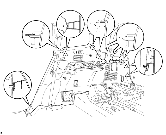
REMOVE DECK TRIM SIDE PANEL ASSEMBLY RH
-
Remove the 3 bolts.
-
Remove the 2 clips.
-
Disengage the 7 claws and 4 clips, and remove the deck trim side panel assembly RH.
-
-
REMOVE ROOF SIDE INNER GARNISH ASSEMBLY RH
Tech Tips
Use the same procedure for the RH side and the LH side.
-
REMOVE COOLER PLATE
-
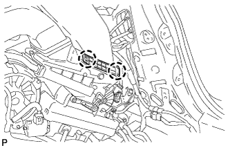
Disengage the 2 claws and remove the cooler plate.
-
-
REMOVE NO. 1 COOLER AIR DUCT
-
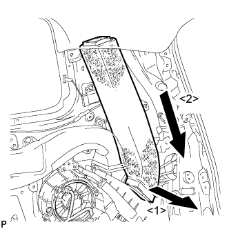
Remove the No. 1 cooler air duct as shown in the illustration.
-
-
REMOVE REAR NO. 5 AIR DUCT
-
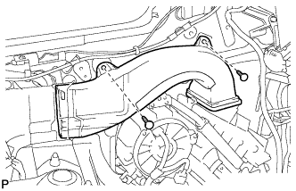
Remove the 2 clips and the rear No. 5 air duct.
-
-
REMOVE REAR COOLING UNIT ASSEMBLY
-
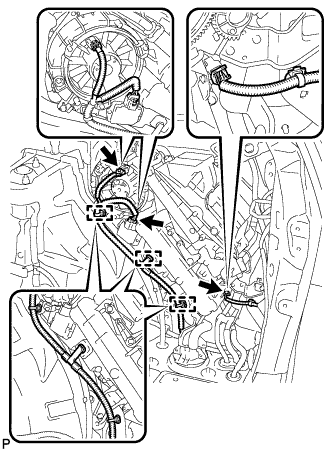
Disengage each clamp.
-
Disconnect each connector.
-
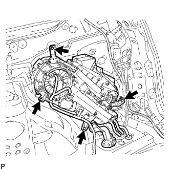
Remove the 4 bolts and the rear cooling unit assembly.
-
-
REMOVE REAR AIR OUTLET CONTROL SERVO MOTOR SUB-ASSEMBLY
-
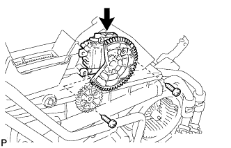
Disconnect the connector.
-
Remove the 2 screws and rear air outlet control servo motor sub-assembly.
-