- Click here
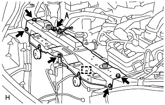
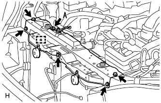
INSTALL COOLER CONDENSER ASSEMBLY
-
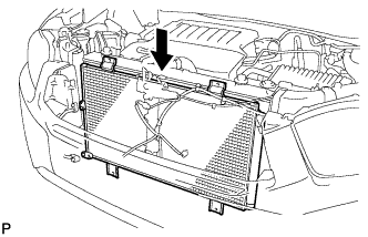
Install the cooler condenser assembly as shown in the illustration.
-
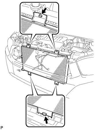
Install the 4 bolts.
Tip:If the condenser is replaced with a new one, add compressor oil to the new condenser.
Capacity 40 cc (1.4 fl.oz.) Compressor oil ND-8 or equivalent
-
- Click here
CONNECT COOLER REFRIGERANT LIQUID PIPE A
-
Remove the attached vinyl tape from the tube and the connecting part of the cooler condenser assembly.
-
Sufficiently apply compressor oil to a new O-ring and the fitting surface of the tube joint.
Compressor oil ND-OIL 8 or equivalent -
Install the O-ring on the cooler refrigerant liquid pipe A.
-
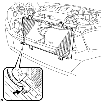
Install the cooler refrigerant liquid pipe A on the cooler condenser assembly with the bolt.
9.8 N*m 100 kgf*cm 87 in.*lbf
-
- Click here
CONNECT DISCHARGE TUBE SUB-ASSEMBLY
-
Remove the attached vinyl tape from the pipe and the connecting part of the cooler condenser assembly.
-
Sufficiently apply compressor oil to a new O-ring and the fitting surface of the pipe joint.
Compressor oil ND-OIL 8 or equivalent -
Install the O-ring on the discharge tube sub-assembly.
-
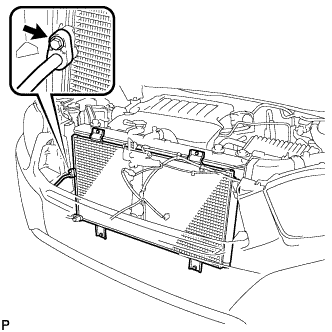
Install the discharge tube sub-assembly on the cooler condenser assembly with the bolt.
9.8 N*m 100 kgf*cm 87 in.*lbf
-
- Click here
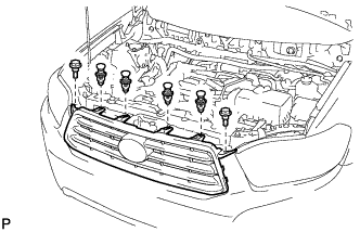
INSTALL UPPER RADIATOR SUPPORT SUB-ASSEMBLY (for LHD)
-
Install the upper radiator support sub-assembly with the 6 bolts and attach the hood lock control cable clamp to the radiator support.
Bolt A 9.8 N*m 100 kgf*cm 87 in.*lbf -
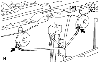
Connect the low pitched horn and high pitched horn connectors.
-
- Click here
INSTALL UPPER RADIATOR SUPPORT SUB-ASSEMBLY (for RHD)
-
Install the upper radiator support sub-assembly with the 6 bolts and attach the hood lock control cable clamp to the radiator support.
Bolt A 9.8 N*m 100 kgf*cm 87 in.*lbf -
Connect the low pitched horn and high pitched horn connectors.
-
- Click here
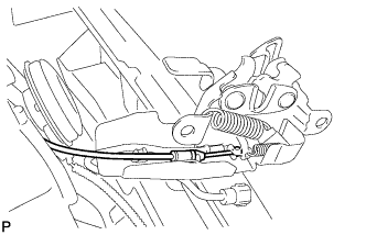
INSTALL HOOD LOCK ASSEMBLY (w/o Engine Hood Courtesy Switch)
-
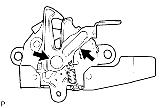
Apply MP grease to the sliding areas of the lock.
-
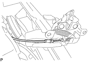
Connect the hood lock control cable.
-
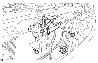
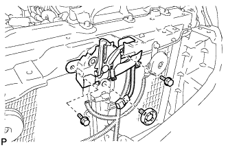
Install the hood lock assembly with the 3 bolts.
8.0 N*m 82 kgf*cm 71 in.*lbf -
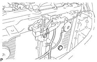
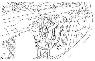
Install the hood lock nut cap.
-
- Click here
INSTALL HOOD LOCK ASSEMBLY (w/ Engine Hood Courtesy Switch)
-
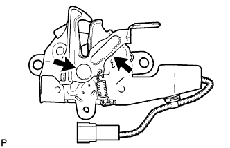
Apply MP grease to the sliding areas of the lock.
-
Connect the hood lock control cable.
-
Install the hood lock assembly with the 3 bolts.
8.0 N*m 82 kgf*cm 71 in.*lbf -
Install the hood lock nut cap.
-
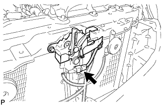
Connect the connector.
-
- Click here
INSTALL RADIATOR GRILLE
-
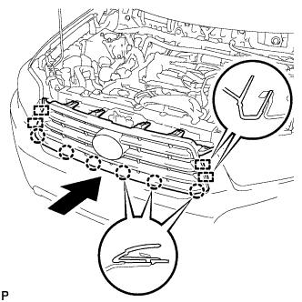
Engage the 4 guides and 6 claws, and install the radiator grille.
-
Install the 4 clips and 2 bolts.
-
- Click here
INSTALL COOL AIR INTAKE DUCT SEAL
-
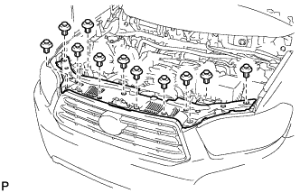
Install the cool air intake duct seal with the 11 clips.
-
- Click here
CHARGE WITH REFRIGERANT
-
Perform vacuum purging using a vacuum pump.
-
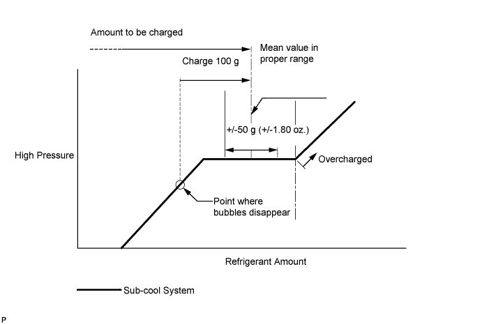
Charge with refrigerant HFC-134a (R134a).
Standard (w/o Rear Air Conditioning System) 550 to 650 g (19.4 to 22.9 oz.) Standard (w/ Rear Air Conditioning System) 720 to 820 g (25.4 to 28.9 oz.) 09985-20010 09985-02010 09985-02050 09985-02060 09985-02070 09985-02080 09985-02090 09985-02110 09985-02130 09985-02140 09985-02150 Note:
-
Do not turn the A/C on before charging with refrigerant. Doing so will cause the cooler compressor to work without refrigerant, resulting in overheating of the cooler compressor.
-
Approximately 100 g (3.53 oz.) of refrigerant may need to be charged after bubbles disappear. The refrigerant amount should be checked by quantity, not with the sight glass.
Tip:Ensure that sufficient refrigerant is available to recharge the system when using a refrigerant recovery unit. Refrigerant recovery units are not always able to recover 100% of the refrigerant from an A/C system.
-
-
- Click here
WARM UP ENGINE
-
Keep the A/C switch on for at least 2 minutes to warm up the compressor.
Note:Be sure to warm up the compressor when turning the A/C on after removing and installing the cooler refrigerant lines (including the compressor), to prevent damage to the compressor.
-
- Click here
INSPECT FOR REFRIGERANT LEAK
-
After recharging with refrigerant gas, inspect for refrigerant leak using a halogen leak detector.
-
Carry out the test under the following conditions:
-
Make sure that the ignition switch is off.
-
Secure good ventilation (the gas leak detector may react to volatile gases which are not refrigerant, such as evaporated gasoline and exhaust gas).
-
Repeat the test 2 or 3 times.
-
Make sure that there is some refrigerant remaining in the refrigeration system.
When the compressor is off: approx. 392 to 588 kPa (4 to 6 kgf/cm2, 57 to 85 psi)
-
-
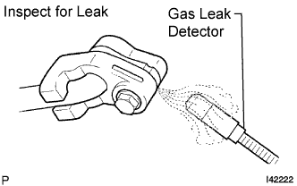
Using a gas leak detector, inspect for refrigerant leak from the refrigerant lines.
-
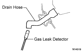
Bring the gas leak detector close to the drain hose with the detector's power off, and then turn the detector on.
Tip:
-
After the blower motor has stopped, let the cooling unit stand for more than 15 minutes.
-
Bring the gas leak detector sensor under the drain hose.
-
When bringing the gas leak detector close to the drain hose, make sure that the gas leak detector does not react to volatile gases.
If it is not possible to avoid interference from volatile gases, the vehicle should be lifted up to allow testing.
-
-
If a gas leak is not detected from the drain hose, remove the blower motor from the cooling unit. Insert the gas leak detector into the unit and perform the test.
-
Disconnect the pressure switch connector and leave it for approximately 20 minutes. Bring the gas leak detector close to the pressure switch and perform the test.
-