LIN COMMUNICATION SYSTEM Driver Side Switch Module LIN Communication Malfunction
DESCRIPTION
The outer mirror switch monitors the LIN communication bus between the components related to the switches on the driver side seat.
Tech Tips
DTC U1127, U1128 and U1129 are output simultaneously when: 1) there is an open or short in the LIN communication bus between the switches on the driver side seat, and 2) their LIN communication bus stops.
WIRING DIAGRAM
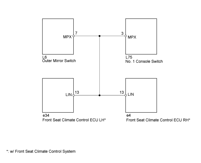
INSPECTION PROCEDURE
Note
When using the intelligent tester with the engine switch off to troubleshoot:
Connect the intelligent tester to the vehicle, and turn a courtesy switch on and off at 1.5 second intervals until communication between the tester and vehicle begins.
PROCEDURE
-
CLEAR DTC
-
Delete the DTC Click here.
NEXT 
-
-
CHECK FOR DTC
-
Recheck for DTC Click here.
Result: Result Proceed to DTC U1127, U1128 and U1129 output occurs A DTC U1127, U1128 or U1129 output occurs B No DTC output occurs C
B 
GO TO DTC CHART Click here
C
USE SIMULATION METHOD TO CHECK Click here
A
-
-
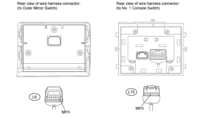
CHECK HARNESS AND CONNECTOR (OUTER MIRROR SWITCH - NO. 1 CONSOLE SWITCH)
-
Disconnect the L6 and L75 switch connectors.
-
Measure the resistance and voltage according to the value(s) in the table below.
Standard resistance Tester Connection Condition Specified Condition L6-7 (MPX) - L75-3 (MPX) Always Below 1 Ω L6-7 (MPX) or L75-3 (MPX) - Body ground Always 10 kΩ or higher Standard voltage Tester Connection Switch Condition Specified Condition L6-7 (MPX) or L75-3 (MPX) - Body ground Engine switch on (IG) Below 1 V
OK
REPLACE OUTER MIRROR SWITCH Click here
NG
-
-
CLEAR DTC
-
Reconnect the L6 switch connector.
-
Delete the DTC Click here.
NEXT
-
-
CHECK FOR DTC
-
Disconnect the L75 switch connector.
-
Recheck for DTC Click here.
Result: Result Proceed to DTC U1127, U1128 and U1129 output occurs A DTC U1127 output occurs B
B
REPLACE NO. 1 CONSOLE SWITCH
A
-
-
CLEAR DTC
-
Reconnect the L75 switch connector.
-
Delete the DTC Click here.
NEXT
-
-
CHECK FOR DTC
-
Disconnect the e4 ECU connector.
-
Recheck for DTC Click here.
Result: Result Proceed to DTC U1127, U1128 and U1129 output occurs A DTC U1128 output occurs B
B
REPLACE FRONT SEAT CLIMATE CONTROL ECU RH
A
-
-
CLEAR DTC
-
Reconnect the e4 ECU connector.
-
Delete the DTC Click here.
NEXT
-
-
CHECK FOR DTC
-
Disconnect the e34 ECU connector.
-
Recheck for DTC Click here.
Result: Result Proceed to DTC U1127, U1128 and U1129 output occurs A DTC U1129 output occurs B
B
REPLACE FRONT SEAT CLIMATE CONTROL ECU LH
A 
REPAIR OR REPLACE HARNESS OR CONNECTOR
-