LIN COMMUNICATION SYSTEM Rear Heater Control Panel LIN Communication Malfunction
DESCRIPTION
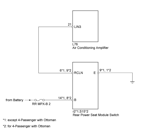
The LIN communication of the components related to the rear heater occurs between the air conditioning amplifier and rear power seat module switch.
WIRING DIAGRAM
INSPECTION PROCEDURE
Note
-
When using the intelligent tester with the engine switch off to troubleshoot:
Connect the intelligent tester to the vehicle, and turn a courtesy switch on and off at 1.5 second intervals until communication between the tester and vehicle begins.
-
Inspect the fuses for circuits related to this system before performing the following inspection procedure.
PROCEDURE
-
CHECK HARNESS AND CONNECTOR (AIR CONDITIONING AMPLIFIER - REAR POWER SEAT MODULE SWITCH)
-
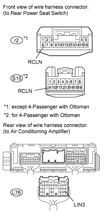
Disconnect the L76 amplifier connector.
-
Disconnect the r2*1 or S15*2 module switch connector.
Tech Tips
*1: except 4-Passenger with Ottoman
*2: for 4-Passenger with Ottoman
-
Measure the resistance and voltage according to the value(s) in the table below.
Standard resistance except 4-Passenger with Ottoman: Tester Connection Condition Specified Condition L76-21 (LIN3) - r2-6 (RCLN) Always Below 1 Ω L76-21 (LIN3) or r2-6 (RCLN) - Body ground Always 10 kΩ or higher for 4-Passenger with Ottoman: Tester Connection Condition Specified Condition L76-21 (LIN3) - S15-9 (RCLN) Always Below 1 Ω L76-21 (LIN3) or S15-9 (RCLN) - Body ground Always 10 kΩ or higher Standard voltage except 4-Passenger with Ottoman: Tester Connection Switch Condition Specified Condition L76-21 (LIN3) or r2-6 (RCLN) - Body ground Engine switch on (IG) Below 1 V for 4-Passenger with Ottoman: Tester Connection Switch Condition Specified Condition L76-21 (LIN3) or S15-9 (RCLN) - Body ground Engine switch on (IG) Below 1 V
NG 
REPAIR OR REPLACE HARNESS OR CONNECTOR
OK 
-
-
CHECK REAR POWER SEAT MODULE SWITCH (BATTERY VOLTAGE AND GROUND)
-
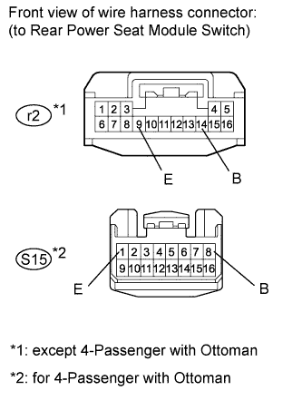
Disconnect the r2*1 or S15*2 module switch connector.
Tech Tips
*1: except 4-Passenger with Ottoman
*2: for 4-Passenger with Ottoman
-
Measure the resistance and voltage according to the value(s) in the table below.
Standard resistance except 4-Passenger with Ottoman: Tester Connection Condition Specified Condition r2-9 (E) - Body ground Always Below 1 Ω for 4-Passenger with Ottoman: Tester Connection Condition Specified Condition S15-1 (E) - Body ground Always Below 1 Ω Standard voltage except 4-Passenger with Ottoman: Tester Connection Switch Condition Specified Condition r2-14 (B) - Body ground Engine switch on (IG) 11 to 14 V for 4-Passenger with Ottoman: Tester Connection Switch Condition Specified Condition S15-8 (B) - Body ground Engine switch on (IG) 11 to 14 V
NG
REPAIR OR REPLACE HARNESS OR CONNECTOR
OK
-
-
CHECK REAR POWER SEAT MODULE SWITCH (OPERATION)
-
Temporarily replace the rear power seat module switch with a new or normally functioning one.
-
for fixed seat type: Click here
-
for power seat: Click here
-
for 4-Passenger with Ottoman: Click here
-
for 5-Passenger with Ottoman: Click here
-
-
Check that the rear air conditioning function is normal.
OK Rear air conditioning function is normal.
NG
REPLACE AIR CONDITIONING AMPLIFIER ASSEMBLY Click here
OK 
END (REAR POWER SEAT MODULE SWITCH IS DEFECTIVE)
-