REAR DOOR SUNSHADE SYSTEM Front and Rear Switch cannot Operate Right Door Sunshade
DESCRIPTION
The rear door ECU operates the motor of the rear curtain (rear door sunshade).
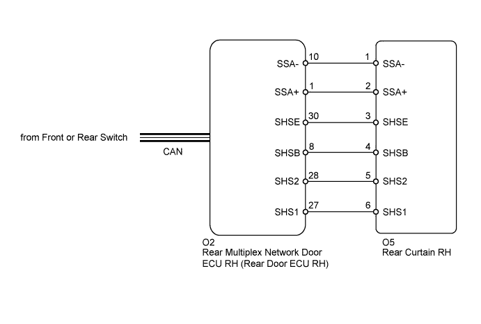
WIRING DIAGRAM
INSPECTION PROCEDURE
PROCEDURE
-
CHECK DTC
-
Clear the DTC Click here.
-
Check the DTC Click here.
Result Result Proceed to No DTCs are output A U0201 is output (for LHD) B U0201 is output (for RHD) C
B 
GO TO CAN COMMUNICATION SYSTEM Click here
C
GO TO CAN COMMUNICATION SYSTEM Click here
A 
-
-
PERFORM ACTIVE TEST USING INTELLIGENT TESTER
-
Select the Active Test, use the intelligent tester to generate a control command, and then check that the rear door sunshade system operates Click here.
Rear Right Door Tester Display Test Part Control Range Diagnostic Note Rear Door Sunshade Operation Rear curtain Up, Down, Stop - OK Rear door sunshade system is operated normally.
NG 
CHECK HARNESS AND CONNECTOR (REAR CURTAIN RH - REAR DOOR ECU RH) Click here
OK 
USE SIMULATION METHOD TO CHECK Click here
-
-
CHECK HARNESS AND CONNECTOR (REAR CURTAIN RH - REAR DOOR ECU RH)
-
Disconnect the O2 ECU connector.
-
Disconnect the O5 curtain connector.
-
Measure the resistance according to the value(s) in the table below.
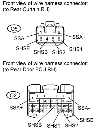
Standard resistance Tester Connection Condition Specified Condition O5-1 (SSA-) - O2-10 (SSA-) Always Below 1 Ω O5-2 (SSA+) - O2-1 (SSA+) Always Below 1 Ω O5-3 (SHSE) - O2-30 (SHSE) Always Below 1 Ω O5-4 (SHSB) - O2-8 (SHSB) Always Below 1 Ω O5-5 (SHS2) - O2-28 (SHS2) Always Below 1 Ω O5-6 (SHS1) - O2-27 (SHS1) Always Below 1 Ω
NG
REPAIR OR REPLACE HARNESS OR CONNECTOR
OK
-
-
INSPECT REAR CURTAIN RH
-
Remove the rear curtain RH Click here.
-
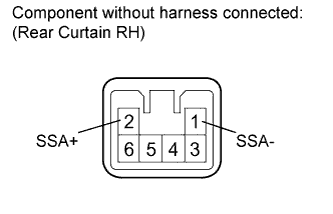
Apply battery voltage and check the operation of the rear curtain RH.
Standard Measurement Condition Specified Condition Battery positive (+) → 2 (SSA+)
Battery negative (-) → 1 (SSA-)
Raises curtain Battery positive (+) → 1 (SSA-)
Battery negative (-) → 2 (SSA+)
Lowers curtain -
Reconnect the rear curtain connector.
-
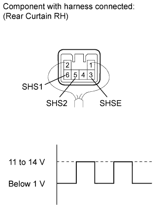
Measure the waveform according to the value(s) in the table below.
Waveform (Reference) Item Content Terminal No. (Symbols)
-
O5-5 (SHS2) - O5-3 (SHSE)
-
O5-6 (SHS1) - O5-3 (SHSE)
Tool Setting 2 V/DIV., 1 msec./DIV. Condition Engine switch on (IG), rear door sunshade switch is pressed OK Waveform is as shown in the illustration. -
NG
REPLACE REAR CURTAIN RH Click here
OK
REPLACE REAR DOOR ECU RH Click here
-